Eng-Tips is the largest engineering community on the Internet

Intelligent Work Forums for Engineering Professionals

stady state dynamic in LS-DYNA

Status
Not open for further replies.

Behdad.S

Mechanical
Oct 29, 2020
9
0
0
DE
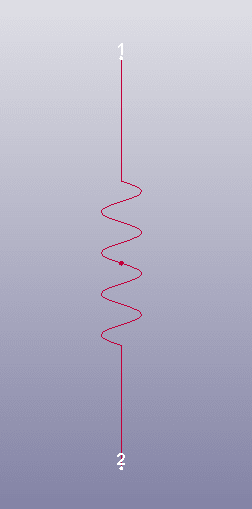
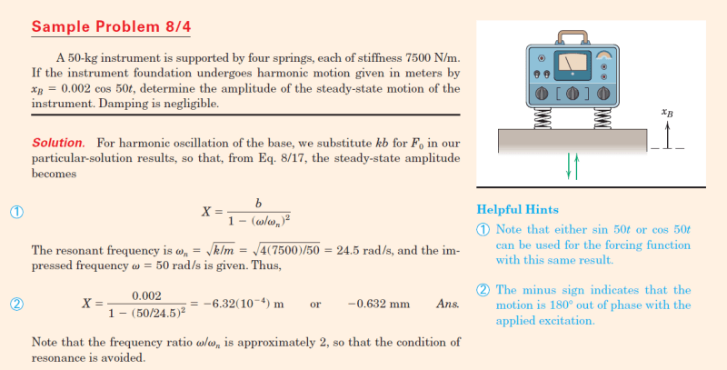
I’m trying to understand how LS-DYNA SSD Module works. For this purpose, I’m solving a simple mass-spring system from a textbook.
problem_fwplqj.png


I tried to solve it with two approaches:
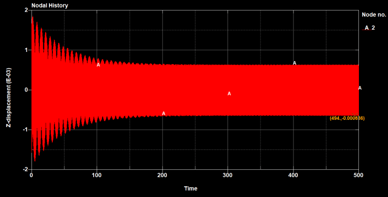
1. Time-domain: The result matches very well with the book.
time_raqmgb.png

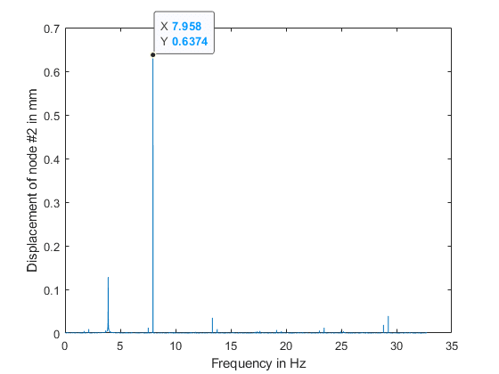
2. Frequency-domain (SSD): unfortunately, I could not replicate the same result. I could not figure out the possible problem. I used enforced displacement by the large mass method. I put both models in my google drive:

Could you help me to understand what my mistake is?
 
Replies continue below

Recommended for you

Could you paste your resulting plot here? And what you are expecting to see?

In the frequency domain, it can be plotted a number of ways - one of which is a displacement ratio (X/Xb) vs frequency ratio (w/wn). This would of course give you a normalized amplitude over a range of frequency...

You also have transients here in the beginning of your signal - so it's unlikely that only the steady-state frequency response would fall out.

 
I have just one excitation frequency; therefore, I expect to see just one number: the displacement in steady-state condition on node 2. The result should match the textbook (0.632 mm)
spring_wxxwno.png


When I use the base displacement method, everything is just right.
Hier is the result of the base displacement method.
Frequency----------Amplitude-translational-z-disp @ 2
7.96E+00 ----------6.32E-04


Your comment about the transient response is absolutely right. An FFT analysis is showing that very well.
ff_bou7th.png
 
Status
Not open for further replies.
Back
Top