Continue to Site

Eng-Tips is the largest engineering community on the Internet

Intelligent Work Forums for Engineering Professionals

  • Congratulations KootK on being selected by the Eng-Tips community for having the most helpful posts in the forums last week. Way to Go!

Standard Fuse Link Selection

Status
Not open for further replies.

Mbrooke

Electrical
Nov 12, 2012
2,546
Does anyone know how to apply "standard" type fuse links to an overhead distribution system?


As its done now type K fuse are applied in series secession as 200K, 140K (recloser coordinated with fuse saving curves) 100K, 65K, 40K, 25K and 15K. 6K for transformers. 8, 12, 20, 30, 50 and 80K links are considered intermediate and thus never used. This achieves 100% selective coordination throughout all branches and their associated spurs.

However, I'm unsure as how or if this pertains to type "S" links.
 
Replies continue below

Recommended for you

You must have very low levels of fault current to be able to coordinate that many levels in series.

Link

See page 5 for k speed with pre-loading, page 3 for standard. You'll coordinate up to 480 A with the 15-25 pair, and 560 A with similar Ks.

 
Done all the time- the fault current levels are acceptable at 200K and 140K, by the time its 6 links in series the lines are already miles out from the substation and it becomes workable especially when most faults are not of the bolted variety. See page 3 (page 9 in the viewer):


However, I'm unsure how to go about selecting S links in that S&C does not state which links are intermediate and which are "preferred", ie:


Typically selecting every other link provides near 100% selective coordination when all is taken into account.
 
According to ANSI C37.42, the "preferred" continuous current values for cutout fuses are 6, 10, 15, 25, 40, 65, 100, 140, and 200 without mention of fuse speed.
 
The guidance about "preferred" ratings works very poorly on my system. Near the substation, the 100 does not event coordinate with a 6. Instead, the coordination chart works well assuming you know the fault values at each fuse location:

I am puzzled what you mean about most faults not being bolted. Have you see significant fault impedance in your typical squirrel or tree branch type faults? For most faults where I have compared event reports to our short circuit model, the fault impedance has been small enough that a bolted fault model is good approximation. Page 3 of the ABB link refers to high impedance faults, which are a totally different category and typically cannot be detected with kind of overcurrent protection.
 
@Stevenal- yup- but "s" links don't come in 140 amps for some reason. I guess its just not what I am familiar with hence my panic/loss of control feelings lol.


@Bacon4life: Arcing presents impedance, as well as coming down on wet asphalt, grass ect after a storm. For example, this:


Notice how the recloser does not trip immediately despite so much conductor being in contact with the roadway.
 
Mbrooke said:

Notice how the recloser does not trip immediately despite so much conductor being in contact with the roadway.

Reclosers don’t trip immediately unless the 50 element is part of the trip equation. What I saw again, and what we went over in our safety meeting regarding this event is different that one would expect just perusing YouTube and watching videos.
 
Correct, just going by a 51 element it was up on the curve- 9 seconds to trip. Wet asphalt adds to the fault loop impedance path. This Youtube video is not a fluke, I've personally seen power lines come down in my town taking time to blow a fused cutout or not at all. One of the greatest misconceptions in the electrical industry is that faults are bolted when the overwhelming majority are not.
 
Alright, an intriguing comparison.


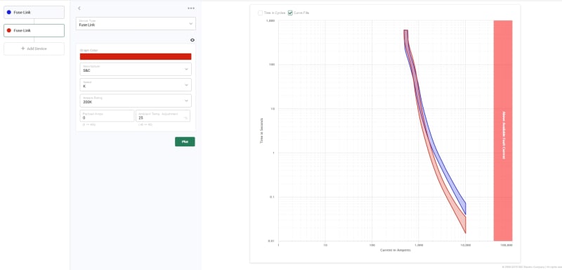
Type 200T and 200K links both start at around 480 amps when cold, mostly identical except for the notable shift towards to bottom.


T_and_K_links_wdmhlt.jpg


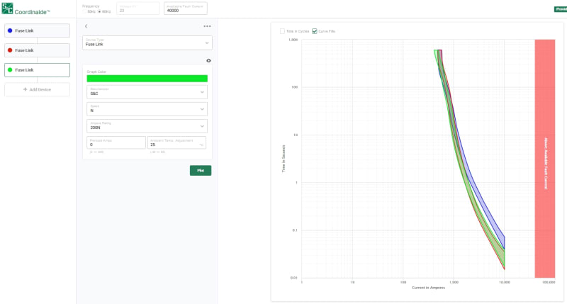
Now, here is the interesting part. N links start at 408 amps, less than T or K links -BUT- the lower part of the curve is is nearly identical to the K link closing following it.

200N_d0khdt.jpg


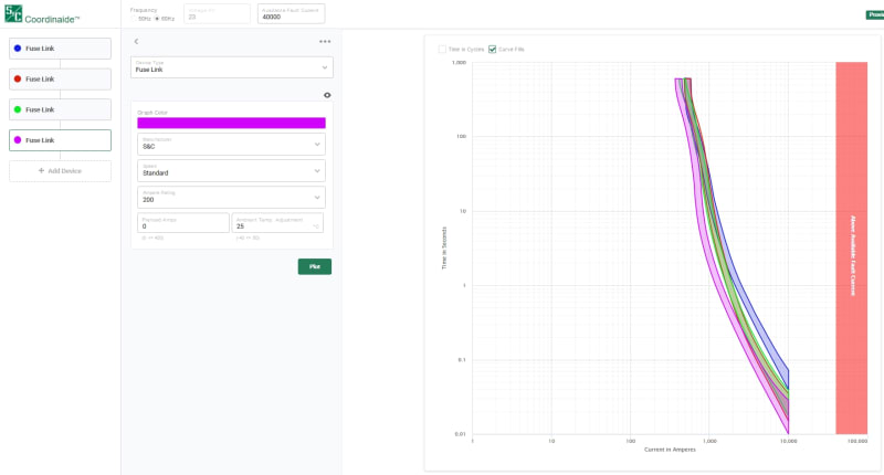
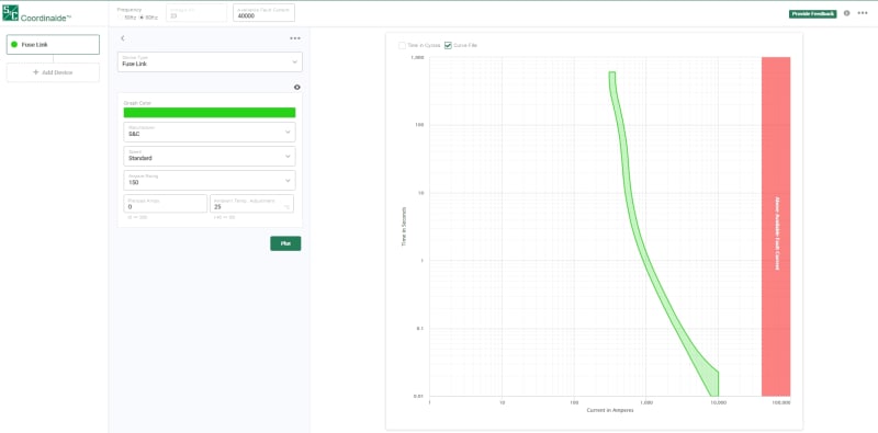
Finally the S link, starts at 366 amps, and is "faster" than than the 3 other fuses.

S_link_xnf3h2.jpg


My question is, why the different pickup settings? I can understand the speed factor, but why start some links below 200% while others at 250%? Why would this matter enough to factor it into the engineering of the link?
 
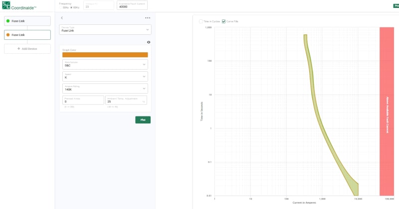
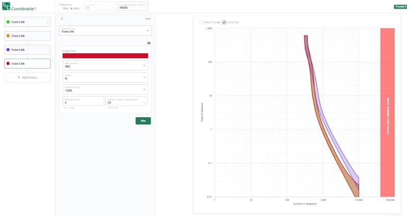
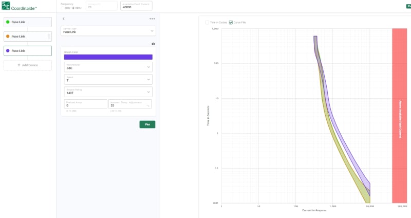
Ok, now I'm really in the twilight... 140K, 150N and 150S links all have an identical time current curve which literally overlays (into one another) identically without showing bare color?

S and K link overlay:

140K_gon5ti.jpg


S link:

150_S_jieyz9.jpg


K, S and N overlay, purple is T link:


150N_ohyk9i.jpg


T link overlay with K and S:


140T_kxk9vh.jpg


Does this mean some links are identical just labelled differently? I suspect that to be the case?
 
Not all the folks who post here are members of other forums and visa versa. LV/code members tend add an interesting perspective to the mix as well.
 
Bolted faults and negligible impedance faults make pretty boring videos; Of the fault videos on YouTube, I expect pretty close to 100% are high impedance faults. High impedance faults are certainly quite scary when they occur.

Perhaps we are spitting hairs between bolted faults with zero fault impedance and faults that have some arcing resistance, but still have current at least 90% of a bolted fault? Or is there a specific resistance value you assume for faults when coordinating fuses?

We installed a few distribution relays with high impedance fault relaying a number of years ago. Based on the data collected from this small sample of relays, most faults had negligible impedance, and of the higher impedance faults recorded, no fuse would have tripped on the high impedance faults. In marketing materials for a high impedance relay, GE suggests 5-20% of faults are high impedance.
 
@Bacon- you make a good point. However- a large chunk of faults (if not the overwhelming majority) occur somewhere on a spectrum between dead zero and high impedance, at least what I tend to call be high impedance. There are plenty of faults where it takes seconds for a fuse link to blow or a recloser to trip when the available short circuit current at the fault point says it should have taken cycles.

When you say arcing limits current to at least 90%, are you talking about peak current or RMS current? At what arc length? Arcing does not just limit current as electricity is passing through ionized nitrogen in real time, but it starts and then stop conducting at differing points in the sine wave resulting in cumulative heating of the fuse link.

Don't get me wrong- I always take dead short values into consideration- but in some cases (such as the first 1/4 mile out from a substation) its not always possible. You simply hope it won't hit the jackpot.
 
Status
Not open for further replies.

Part and Inventory Search

Sponsor