Eng-Tips is the largest engineering community on the Internet

Intelligent Work Forums for Engineering Professionals

Starting Methods for Brushless Synchronos Motors

LargeACMotorDude

Electrical
Sep 11, 2023
9
0
0
US
Hello,

I’m looking for some information on the controls and logic for starting a brushless synchronous motor.

Any references or resources for these shorts of motors and controls would be greatly appreciated. I just find them interesting and would like to understand them a bit better.

Thanks!
 
Replies continue below

Recommended for you

It will generally use the amortiseur* winding to start the motor as an induction motor.
An internal, rotating circuit will apply the field at the optimum time.

*The damper winding (also amortisseur winding) is a squirrel-cage-like winding on the rotor of a typical synchronous electric machine.

--------------------
Ohm's law
Not just a good idea;
It's the LAW!
 
Hey thanks Waross,

I should have been more specific in my original post. I am primarily concerned with the transition from the amortiseur winding to the rotors poles.

The reason I’m looking into it is we’ve had some questions on sync motors failing to synchronize. I’m training to gain a better understanding of the controls and sequencing aspect of syncing the poles.

 
Generally, you apply power to the stator and let the motor accelerate. When it reaches pull-in speed you apply power to the brushless exciter field winding which then applies the field to the rotor. You either use time or you use external speed detection methods to determine when to apply the field. You can monitor motor power to ensure it synchronized.
 
All the steps:
1) Check that all the necessary "required to run" auxiliaries are powered up and doing what they should (i.e. fans moving air, pumps pumping fluid, etc.).
2) If the excitation circuit requires an external power source (e.g. the nameplate reads excitation requirements as something less than 300 V and a current below 10 amps), make sure the excitation power source is ON. This powers the exciter stator winding.
3) Close the breaker to the main stator circuit. This energizes the main stator winding at nameplate voltage, or whatever voltage the soft starter is set to produce.
4) Let the synchronous rotor spin up toward synchronous speed. This is happening because the amortisseur winding is acting like a cage on a squirrel cage induction machine, creating what is known as an inductive start.
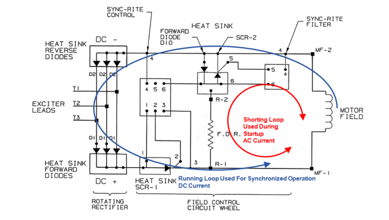
5) The "brains" on the rotating rectifier portion of the exciter circuit will check for two things: a) sufficient voltage buildup to properly operate the silicon-controlled rectifier (SCR) which rectifies the AC power created by turning the exciter rotor (a wound rotor induction winding) inside the magnetic field of the exciter stator, and b) a low enough frequency differential between rotor and stator voltage waveforms (i.e. approximately 3-5% slip).
6) Once conditions are correct, the "brains" trigger the SCR to allow current to flow to the main synchronous rotor winding, causing the machine to "pull in" to synchronism. It should ALSO trigger another rectifier to open-circuit, taking the field discharge resistor (FDR) - if there is one - out of the circuit.

Problems on starting are usually one of the following:
A) Incorrect field current to the exciter from the exciter supply (should be set for unity power factor value).
B) Power factor relay is tripping the system out because the time delay isn't long enough to get the motor up to speed, thus the "observed" power factor is way down in the mud.
C) The load is higher than what the synchronous machine can handle - which is quite a bit lower than a squirrel cage induction, for instance. This may be a result of material left in the process from the previous stoppage or may be simply a different condition (all louvres closed, for instance, creating a higher-than-expected back pressure).
D) Damage to the rotating control wheel - most commonly, the fine wires that run from the "brains" to the SCR gate terminals.
E) Damage to the "brains" unit itself.

Important - if the signal to the SCR controlling the FDR portion of the circuit is inactive and the FDR remains in the circuit at synchronization, there is a reduced torque present (some of the energy being wasted in the FDR). This may take the machine out of synchronism almost immediately or may create a condition where synchronism is impossible to begin with.

Converting energy to motion for more than half a century
 
You either use time or you use external speed detection methods to determine when to apply the field.
Maybe not a good idea.
The phase angle between the back EMF and the grid is critical.
Out of phase application of the field may result in extreme transient currents and possible physical damage.

Before the development of brushless excited synchronous motors a field frequency relay was used to determine when two variables were suitable for application of the field current.
1. The speed was sufficiently high to allow successful synchronization and,
2. The phase relationship between back EMF and the grid was suitable to synchronize without objectionable transients.
With a brushless exciter, an internal, rotating circuit performs these functions.

WEG/E-M website said:
Sync-Rite Plus™ Controller
Industry leading synchronous motor starting control, now with the added benefits of data logging and
wireless streaming technology.
J Reliably synchronizes any brushless synchronous motor
J Interchangeable with all legacy Sync-Rite™ models
J Monitors and records: field voltage, field current, FDR status (in
or out of circuit), and firing of SCR-1
J Customizable control settings allow controller to be optimized
for various motors and loads
J Slip sync speeds from 90% to 99.5%
J Zero slip sync times from 2 to 5.5 seconds
J Wireless transceiver for streaming data and downloading data
records without shutting the machine down
J USB port allows data to be gathered when the machine is
not running
J Starting records provide an invaluable tool for solving
synchronization issues should they occur
J Average records track changes in the operating conditions of
the machine to identify issues early, allowing users to take
corrective actions before issues become serious
J Original Sync-Rite™ Control’s green and red indicators and a
new blue indicator that gives positive Sync-Rite Plus™ Filter
confirmation that the motor has been synchronized
Sync-Rite Plus™
Typical Synchronization Waveforms
Link to synchronous starting info.
Screenshot_2024-09-15_at_12-13-55_WEG-synchronous-motor-handbook-031.0-brochure-english.pdf_h5rrzj.png


--------------------
Ohm's law
Not just a good idea;
It's the LAW!
 
Bill,

There are very few motors that internally control the field application. So few that I don't see any, maybe once in all the time I've dealt with brushless motors. WEG sells motors without SCR-1 and the control circuit. that part is an option and they tend not to sell that part. I've seen the motors without it and started them.

However, if it did contain such a circuit, then applying the exciter field when the motor was UTS would work just fine because the circuit would still power up and then the logic could determine the main field should be applied.

Finally, a lot of the synchronous motor applications start unloaded and in those cases the motor will reluctance synchronize. At that point, you apply the field regardless of it being in phase or not. 50% of the time it has to slip a pole because it reluctance synchronized with the poles magnetized the wrong way. I've seen this many, many times.
 
Back
Top