Continue to Site

Eng-Tips is the largest engineering community on the Internet

Intelligent Work Forums for Engineering Professionals

  • Congratulations GregLocock on being selected by the Eng-Tips community for having the most helpful posts in the forums last week. Way to Go!

Steam state (p,T) between nozzle and impulse turbine wheel

Status
Not open for further replies.

Proc9

Industrial
Oct 11, 2017
5
Hello,

I am trying to calculate the state of steam between the nozzle and impulse turbine wheel for tip and labyrinth leakage purposes for a specific steam loss model, and having some troubles with it.
Using _0 before nozzle, _1 after nozzle but before turbine blades, and _2 after turbine blades. I have the following information from process (simplified):

p0 = 1600 kPa
p2 = 500 kPa
T0 = 350 C
T2 = 250 C

Calculated/figured the following values:
h0 = 3147 kJ/kg
h2 = 2961 kJ/kg
Δh = 186 kJ/kg
v0 = 60 m/s
v1 = SQRT(2000*Δh+v02) = 612 m/s

Assumed nozzle speed ratio v1/v1,is = 0.95

In isentropic case (ratio is 1):
Δhis = 186/0.952 = 206 kJ/kg, so nozzle loss therefore is:
hn = Δhis-Δh = 20 kJ/kg (and v1,is = 644 m/s)

But my major question is, how do I combine all this information? I don't know the isentropic efficiency for turbine wheel (without nozzle) either. I was going to solve it after knowing (p1,T1), since I can calculate the isentropic efficiency for nozzle+wheel combination using p0,T0 to p2,T2 (which is 0.65, fairly common for Curtis wheel). Seems I am missing some theory behind this. Can someone shed some light on how to proceed with this? Nozzle loss should be loss in flow energy (644 -> 612), increase in temperature and loss in entropy as far as I know.

I tried to calculate h1=h0-hn and combine that with p1=p2. What actually happens with the temperature T1 in relation to T0 or T2?
How can I account velocity in (p,T,h,S)-table? I have a software to calculate Curtis wheel's isentropic efficiency using (pin,Tin,is%,pout) so I can't account velocity in as input variable? If I use p2 as p, I get 0 W power obviously.
And is the energy transfer in wheel 186 kJ/kg * nwheel,is% or (186-20)=166 kJ/kg * nwheel,is%? is% = isentropic efficiency in wheel

If p0 > p1 > p2, how can I calculate it? Can I assume incompressible flow and use Bernoulli equation p1 = p0 + 1/2 ρv02 - 1/2 ρv12 (assume ρ=ρ01 with enough accuracy) and look for T1 through h1=h0-hn?
 
Replies continue below

Recommended for you

Unfortunately, you are deep inside the very complex, hence very difficult, hence very proprietary turbine blade aerodynamics and steam transitions. The big companies (GE, Siemens, Toshiba, etc) don't want you (us) to know their secrets and their approximations. And the big universities - if they have grants to study it in the CAD-FEA computers - get wrapped up in restriction clauses.

Try an iterative approach, assuming no condensation (Ideal gas) for a start and an assumed efficiency for that stage. Get the numbers close for the ideal gas. You will be wrong, but be closer than nothing. (Why impulse blade? ) LP turbine outlet are very wet, but IP or HP turbines are non-condensing (typically).

Then, but only after you have reasonable numbers for an ideal gas, change to a compressible gas. Then change to a condensing gas.

YOu need actual numbers for each stage for temperature, pressure, percent of water.
 
Hello,

Forgot to mention, this turbine is one-wheel HP turbine (impulse, Curtis wheel) so condensing / wet-% shouldn't be a problem as shouldn't exist in this only stage.

So if I assume nozzle speed ratio to be 0.95, the efficiency for the nozzle is around 0.9 (0.952 if you don't account v0).

Since I know the whole stage's isentropic efficiency (p0, T0 to p2 with entropy constant is is-100%, and I know the real enthalpy drop because of process data sensors), can't I assume that nozzle efficiency * wheel efficiency = ~stage efficiency?

So after these stages I should be able to make a raw approximation about p1 and T1, but still can't figure out how.
 
First - how accurate do you need to be? on a typical impulse stage you can approximate that the nozzle is doing all the work and it takes all the pressure drop. This will help you.

A curtis wheel is basically a single stage turbine except that the power needed to be split over two buckets because there wasn't a single bucket choice that was suitable. In this regards the second set of nozzles can be treated as just turning the direction of the flow and takes no drop across it.
 
Hello,

Yes, I have assumed all enthalpy drop (186 kJ/kg, isentropic case 206 kJ/kg -> loss 20 kJ/kg) to be in the nozzle set, but I am a little lost how to calculate the state after I have lost all kinematic energy generated with nozzle.

I highly doubt the state which counts as leakage loss in labyrinth seals before the blade but after the nozzle is same as before the nozzle, so what would be a raw approximation for it? Does it have:
1) around the same pressure 1600 kPa and enthalpy 3147 kJ/kg as before the nozzle
2) around the same pressure 1600 kPa and enthalpy 3147-20 kJ/kg (nozzle loss) as before the nozzle
3) significantly lower pressure than 1600 kPa but bigger than 500 kPa and enthalpy 3147 kJ/kg same as before the nozzle
4) significantly lower pressure than 1600 kPa but bigger than 500 kPa and enthalpy 3147-20 kJ/kg (nozzle loss) as before the nozzle
5) pressure does not change significantly after the nozzle back to previous state and real enthalpy drop is converted to friction
6) pressure does not change significantly after the nozzle back to previous state and real enthalpy drop-nozzle loss (186-20 kJ/kg) is converted to friction?

So which of these scenarios would be the closest approximation in this case, or is there another alternative?
Basically I have to calculate both tip loss for the blade (where kinematic energy remains for most part) and more importantly the steam leakage ratio over labyrinth seals (where all kinematic energy is lost).
 
Bring it back to basics... you will not get your accuracy your looking for to get leakage flow at any high probability without CFD or years of model coorilation.

Assume its an ideal nozzle (100% throttling device). The all of the energy for that particular stage will be converted to kinetic through the pressure drop accross the nozzle only. This assumes 100% impulse bucket with no reaction along the length (small bucket heights). So in this case, the pressure on the entrance side of the nozzle will be higher than the exit edge of the nozzle. Assume no energy is lost and enthalpy is maintained (you havnt extracted any useful work yet). So a decent approximation is that the pressure between the bucket and nozzle is the same as the exhaust pressure just after the blade, meaning the pressure is the same before and after the bucket. . You can use like a .97 factor to adjust pressure to get a better approximation, but i doubt your in the realm of this accuracy anyways.

 
Hello,

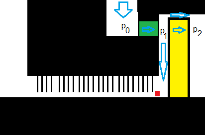
Yes, I have figured this part out that the pressure is the same after the nozzle and after the bucket (afterall, this is the theory behind impulse turbine) but currently I am looking for the pressure before the labyrinth. I used my magical MS Paint skills to draw a picture.

Yellow is the Curtis wheel, green is the nozzle, red is the spot I am interested in. If I assume v = 0 in that spot, should I have similar pressure as p2 (which is same as p1)?
So question in more simple form is, should I approximate the pressure in red spot to be same as it, or p0 - pressure loss from p1 to red due to high velocity? Or just assume that about all velocity is converted into heat so it would be isenthalpic process between p0 and red point, but pressure is same as p1?

forum_zamf9y.png
 
The pressure and also BTU/lb at the red spot can be approximated with little error as P1. The P1 pressure will fill that entire cavity between the exit edge of nozzle and the rotor shaft with negligible variation for your purposes.

The flow will be determined by P1 / Pleakoff (assuming it goes to some other pressure controlled lined) and the flow coefficient of your packing.
 
Hello,

Thanks for the advise. What do you mean by Pleakoff?
 
Just ASSUMING here is that you have multiple packing with intermediate pressure between and not just a single shot like you shown of P1 down to Atmosphere. Pleakoff for a multistage turbine is tapped at a following stage to control the pressure and limit the amount of leakage flow. I havn't looked at a single stage in a long time but the last one I remember used a controlled line somewhere else in the plant to dump steam and control that flow. Your setup may be different and just use a much higher restriction (more teeth) to counter the higher driving force (more deltaP).

typical arrangement

Atmos 14.5 psia ~18psia Pleakoff (150 psia??) P1 (Nozzle exit press)
 
Status
Not open for further replies.

Part and Inventory Search

Sponsor