Continue to Site

Eng-Tips is the largest engineering community on the Internet

Intelligent Work Forums for Engineering Professionals

  • Congratulations waross on being selected by the Eng-Tips community for having the most helpful posts in the forums last week. Way to Go!

Steel beam bearing on Precast 1

Status
Not open for further replies.

Samwise Gamgee

Structural
Oct 7, 2021
113
US
I have a condition where a steel beam needs to be bear on precast. Can we directly bear the bear on precast for about 4'-0" . Or do I need to elevate it and put in on a shim stack ?

Point A is supported by other precast and has an embed that will take all of the gravity load there. However, I was not sure what needs to be done on the other side. I also need to have lateral restraint to be provided for in plane forces. Can I drill and connect through the flanges and connect it to the precast ?
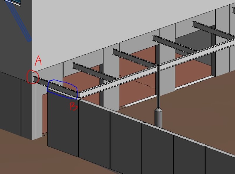
Capturea_ximzty.jpg
 
Replies continue below

Recommended for you

I think you'd be better served with one or two discrete weld plates installed in the pre-cast as opposed to bolts down through the beam flange into the top of the wall.

I think you certainly could just bear it down on the wall without the shim stacks. But I'd also be designing it as if it only had point bearing at the end of the beam for the beam design, and maybe point bearing at the end of the wall for the wall design (to envelope design around the worst case loading scenarios for each piece).
 
So the tricky thing I just heard from the Architects is that there is a gap between the precast and the bottom of steel. I was planning on doing something like this . What do I need to take care of if the anchor rods are being exposed. And also anything that I need to be aware of for drilling holes through the beam flanges ?

Capturea_drwqmp.jpg
 
That detail is not a good idea. First of all, those anchors are too close to the precast walls (breakout will likely govern and you can probably not make it work), and you will probably hit rebar in the precast wall if you drill at those locations. Secondly, exposed anchors create transversal bending (i.e. torsion) of the lower flange, which is not good.

What are the loads on that steel beam? If they are small, you are better off just using a sliding connection, i.e. placing the beam on rubber bearing pad (width = wall thickness, length = 0.1,...,0.3*wall_length). The bracing is handled by the rest of the frame, i.e., by connecting the beams at point B with a connection that matches the boundary conditions assumed in your calculation model.
 
Is this just a canopy? what are your loads. If youre having a lot of trouble with the precast free standing wall, i might just cantilever this beam over the nearest column to pick up the beam. Looks like ~~15-20ft? You mentioned in plane loads too. Where are those coming from?

sp20211104_090117_843_s1s5gs.png
 
centondollar said:
What are the loads on that steel beam? If they are small, you are better off just using a sliding connection, i.e. placing the beam on rubber bearing pad (width = wall thickness, length = 0.1,...,0.3*wall_length). The bracing is handled by the rest of the frame, i.e., by connecting the beams at point B with a connection that matches the boundary conditions assumed in your calculation model.

So I ended up doing something similar. I connected the beam in red to the cross beam and ended up just adding a grout pad for the cross beam. This was working.

1_ed0y5f.jpg
 
dold said:
Is this just a canopy? what are your loads. If youre having a lot of trouble with the precast free standing wall, i might just cantilever this beam over the nearest column to pick up the beam. Looks like ~~15-20ft? You mentioned in plane loads too. Where are those coming from?

The span is significantly larger , so I can't cantilever the beam without making it a bigger beam (which I want to avoid) . This is what I ended up doing.

1_ynchzw.jpg


The in-plane loads are coming from the 2'-0" tall façade that is around the canopy on all sides like shown here.

2_jj3xsw.jpg
 
How are you resisting the out-of-plane panel demand with just a grout pad?
 
My eyes may be failing me, but wouldn't the long beam be placed first? and the short beam fastened to it? For erection purposes?

Rather than think climate change and the corona virus as science, think of it as the wrath of God. Feel any better?

-Dik
 
Dik, that makes sense. Also, if the long beam is deeper, that will drive the erection sequence to maintain top of beam elevation as I'd imagine the short beam to have less depth. If you try to bring the long beam in 2nd, there might be a conflict.
 

I missed this thread earlier... I'd use a single cast in plate with headed studs and weld a single fin plate to it and bolt the beam to the fin plate. I'd don't know why you show 4 bolts; are your loads that high? I would have thought 2 bolts with a single plate would be lots (I don't like using 1/2" dia bolts) [pipe].

You could use a cast in T section with headed studs, since the back face of the panel is the one away from the form usually, and the assembly could be HDG. If not back face, then a flat plate for welding as mentioned earlier.

Rather than think climate change and the corona virus as science, think of it as the wrath of God. Feel any better?

-Dik
 
Status
Not open for further replies.

Part and Inventory Search

Sponsor

Top