Continue to Site

Eng-Tips is the largest engineering community on the Internet

Intelligent Work Forums for Engineering Professionals

  • Congratulations KootK on being selected by the Eng-Tips community for having the most helpful posts in the forums last week. Way to Go!

Steel beam on top of ICF wall detail 2

Status
Not open for further replies.

Rich Zimmerman

Mechanical
May 11, 2019
27
I've got a steel beam coming in perpendicular to an ICF wall). It sits on top of the wall (no pocket per-se). Both ends of the beam are supported the same way. Normally I would just drop a bearing plate with non-shrink grout and then weld the beam to the plate at the job site. However on-site welding requires a special inspection by an engineer and a trip from a welder and it occurs to me that perhaps I could just work something up where the beam gets bolted to the top of the ICF wall somehow.
So, two question:

1. Anyone have a detail where the beam gets bolted to the wall rather than welded to a bearing plate? I'm thinking a couple 5/8" bolts at the beam gage through the bottom flange set maybe 8" into the ICF. Am I missing something important here?

2. It occurs to me that the design might allow me to drop the beam a few inches and mount it into a pocket. After the beam is set, grout around it. So, in that situation would I have to weld the beam or would the grout around the beam serve to hold the beam from moving.
 
Replies continue below

Recommended for you

By the way, it's a W14x26 beam, 20' long (support only at the ends via the detail we're talking about). Braced by floor joists. My calcs show roughly a 1.2 kips/ft uniform load across the span. By my calcs with a 4" bearing surface I shouldn't need transverse stiffeners over the ICF.
 
If you want a post installed option, put a bearing plate wider than the beam flange that’s shop welded to the bottom of the beam, then use epoxy or screw anchors to attach down into the the wall.
 
Maybe a steel column beside the wall is your best option. I don't think those insulated walls deal well with point loads.
 
My first choice would be txeng91's suggestion with the wide baseplate. A couple other notes:
[ul]
[li]If there isn't any uplift or any significant load passing through the anchors, 8" embedment is overkill.[/li]
[li]A W14x26 is 5" wide...a fairly tall and skinny beam. I'd be inclined to put a pair of stiffeners in the ends. For bottom bearing beams I lean towards a stockier section anyway - for example, you could use a W12x30 (6" wide)...it would give you comparable properties and only an extra 80 lbs of steel.[/li]
[/ul]
 
I've detailed a base plate with threaded rods into the concrete that would be fixed to the beam flanges. only issue is placement. the concrete guys around here arent the most precise in placing those.
regarding the icf with the point load. if it falls within the icf tables then not an issue.
I've had some projects where I had to add steel in the concrete to act as a column to transfer the load.

p
 
If it is locked in by the joists, do you even need to attach it to the wall? I typically don't. Maybe in earthquake country you need to. You could go directly thru the bottom flange but they will be drilling at an angle - will probably still work as long as the holes are oversized a bit.
 
Thanks everyone for suggestions.
CANPRO: I didn't put stiffeners because I calculated with an overall load of 24kips I've got 12kps on each end. Even a small 4" bearing on a W14x26 has crippling/yielding at 18/19kips respectively, and I'd certainly do at least 3" bearing. Perhaps a shorter beam would be better though just because my floor is 14" thick, so I have to powder drive the hangers directly to the beam flange. With a 12" beam I could put a wood runner on top and nail into it.

XR250: You don't secure the beam to the wall even when it just sits ontop of the wall? I can see not securing it if it's in a beam pocket as it can't really go anywhere. Plus, doesn't not securing make the supports go from "pinned" to "simple"
 
If you're going to use a base plate with post-installed anchors, keep in mind that some jurisdictions need post-installed anchor special inspections. If you use cast-in-place anchors in this particular situation, as pmtrevisan1 mentioned, quality control is bad but I've used anchor bolt sleeves in footings (not walls) but it might be something to look into. This allows some adjustment before grouting it. I'm sure someone will correct me if this is horrendous advice.

I'm not sure what's going on above the ICF wall and how you're connecting your diaphragm to it. If the steel beam is sitting atop the ICF wall, there needs to be a way to connect the floor diaphragm to the shear wall.

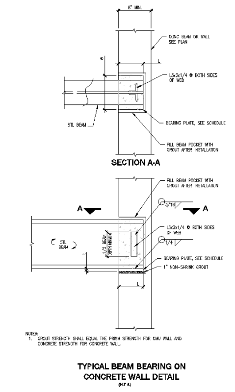
If you're not in a seismic zone, no uplift, and if the ICF wall is continuing up to the next level, you could weld small angles (say L2x2x1/4) to each side of where stiffeners would be to prevent the beam from pulling out. Then you can neglect anchor bolts entirely. I'm not at work so I can't send the detail, but I will. It's for a regular concrete wall but it also applies to ICF.

Also, a 12" beam with a wood runner is much easier to work with than joist hangers with power actuated fasteners or welding.
 
Thanks milkshakelake, The ICF wall stops on one side but continues up another 4' on the other. Hard to describe so I drew this picture. It shows the framed 2nd story on the beam and the I-Joists attached to the beam. The plan view is shown underneath. The ICF constitutes the walls for the 1st story (which is 12' high on the left half and 8' high on the right half). The 2nd story sits ontop of the 8' section and then continues over a small river where it picks up a steel post on the opposite side.

So I'm thinking your method won't quite work here. I also don't think the "weld a large bearing plate to the flange and bolt through that" will work either because I'm up against that 12' section on one side.
 
I double down on my recommendation for stiffeners at the ends. Your beam is loaded one side only and has a wall on top - you need some lateral stability at the end of your beam. Its not just a web crippling issue.

 
Rich Zimmerman said:
XR250: You don't secure the beam to the wall even when it just sits ontop of the wall? I can see not securing it if it's in a beam pocket as it can't really go anywhere. Plus, doesn't not securing make the supports go from "pinned" to "simple"

My thinking is the wall ain't going to move sideways and the top of the beam ain't either if it is connected to the floor diaphragm (and assuming the floor diaphragm is shear-ly attached to the wall) so it comes down to being a web crippling issue that needs to be checked.
 
There was a thread here last week where people expressed their opinions on using stiffeners in these situations. For most beams in a residential applications, I'm probably not using stiffeners. In this case, I'm definitely putting in stiffeners.

You only have floor on one side - which will cause your beam to rotate. The top mounted hanger you're showing will do nothing to provide rotational restraint. In addition, you're top loading the beam (joist and wall), which is inherently less stable.

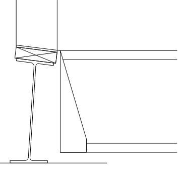
Again, this is not just a web crippling issue. Below, I've drawn a rough version of your section - the beam is drawn at the extreme end of its allowable tolerances (out of square). You could potentially have a beam that is that out of square on your project. Using the stiffeners will keep your beam from rotating and help deal with any initial imperfections.

w14_i6t5nq.png
 
Good point CANPRO. Seems like we have a local bending and global torsion issue that is gonna be tough for a W-section to accept. Might need to use an HSS and brace the ends. I will typically try to use a beam that is shorter than the joists, face mount hangers and tie the bottom of the beam to the bottom of the joists with welded straps to resist the torsion and eliminate the flange/web bending.
 
I see your point CANPRO although typically you put stiffeners where the point loads are. Usually that's at the end or wherever you have a vertical column coming down to your beam. Here you've basically got a series of point loads wherever there's an i-Joist. The point loads at the end (The supports) don't technically need a stiffener.
Surely you're not suggesting a stiffener every 12" next to each I-joist. So you're suggesting stiffeners at the ends to help counteract beam torsion. Maybe this is a classic example calling for a closed shape that'll resist torsion. Or more likely I'll just drop a stiffener at the ends and maybe another one in the middle for good measure. Thanks!

However, I still don't have a good means for attaching the beam to the ICF.
 
txeng91 said:
If you want a post installed option, put a bearing plate wider than the beam flange that’s shop welded to the bottom of the beam, then use epoxy or screw anchors to attach down into the the wall.

I'm curious about this as I'm in the process of trying to create a similar detail. Normally, I'd veto this as not providing any way to adjust the elevation of the beam. has that not beam a problem for you?

 
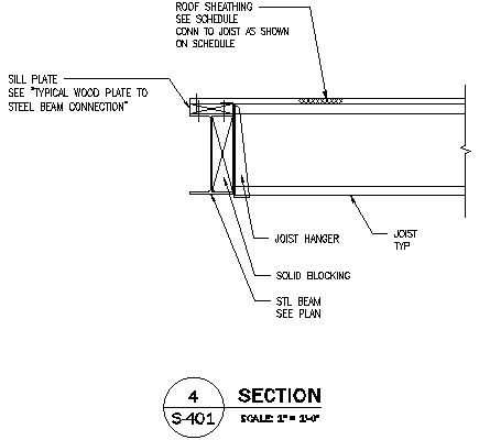
One way to take care of the torsion problem is to run wood blocking along the web and connect the joist hanger to it. Though I never head of a steel beam twisting due to wood or cold formed steel joists. This detail isn't the best, I forgot to show the connection of the solid blocking to the steel beam, but you get the idea.

Capture_pvgklt.png


And this is the beam on wall detail I use just for reference, though you mentioned it won't work for you.

Capture2_apiwkv.png
 
milkshakelake, what's your typical callout for "typical wood plate to steel beam connection". Thinking 1/4" screws 1-1/2" long, alternating from one side of the web to the other spaced 12", with two of them at 6" from end of the beam. Was also thinking of powder actuated fasteners, but I don't think they'd have the pullout resistance.
 
You may be surprised at the pullout capacity for PAFs. I'd give them a look. My typical spec for wood being fastened to steel is PAFs unless the uplift/tension loads are quite high, in which case I normally would require a different connection detail anyways then just to the wood nailers.
 
Rich - can you still do the baseplate and just have a couple anchors off to one side? Seems like you just want some sort of anchorage to the wall and there’s not really any significant force on them. Also don’t think this application would warrant special inspection.

For the wood to steel connection. The flange will probably be to thick to screw through. I usually spec threaded studs welded to the beam or powder actuated fasteners. If your worried about pullout you can spec steel washers on the powder actuated fasteners.

Kootk- I’ve only used it on CMU but I believe they should be able to use shims and/or grout to adjust the elevation.
 
Status
Not open for further replies.

Part and Inventory Search

Sponsor