Continue to Site

Eng-Tips is the largest engineering community on the Internet

Intelligent Work Forums for Engineering Professionals

  • Congratulations cowski on being selected by the Eng-Tips community for having the most helpful posts in the forums last week. Way to Go!

steel beam splice; stringent deflection criteria 1

Status
Not open for further replies.

Ben29

Structural
Aug 7, 2014
324
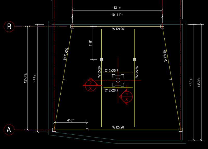
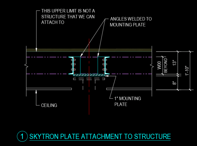
I have a job where we are designing a steel support structure to be installed inside an existing medical office to support a new medical equipment apparatus. The apparatus will put a moment of 4.8 ft-k on the steel support beam. and the plate that it is all attached to cannot rotate more than 0.16 degrees. Existing conditions prevent us from hanging the apparatus from the exiting structure.

On top of this, the new beams (which range from 12ft - 14ft long) will need to be spliced so we can get them into the building.

Would you suggest using slip critical bolts on the flange plates for the splice? Can anyone refer me to a design guide for beam splice designs?

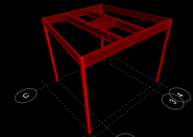
Here is a screen-shot of the steel support we are designing. The medical boom apparatus will be hung from the center area.

oem_frame_wx0oyb.png
 
Replies continue below

Recommended for you

Is welding not allowed, or is it just attempting to avoid it?
 
jayrod, welding is allowed
 
Wouldn't that be more rigid than even a slip critical bolted connection (I guess in theory a slip-critical connection should perform as adequately). Then you shouldn't really be worried about the splicing aspect, and more just about the stiffness of the system.
 
OK - I will double check with the contractor and try to go that route. Thank you.
 
A full bolted field splice (with flange and web plates) with fully tensioned bolts (slip-critical connection) will be somewhat stiffer than a continuous beam, at least up to the slip force. The latest couple editions of the AASHTO LRFD bridge design spec have a simplified splice design procedure. I believe there's still free design software available beam/girder splices, also.

Rod Smith, P.E., The artist formerly known as HotRod10
 
Once the equipment is installed what loads are on it that would promote deflection or rotation? Can it be accommodated by adjustment? and slip critical/welded connections?

-----*****-----
So strange to see the singularity approaching while the entire planet is rapidly turning into a hellscape. -John Coates

-Dik
 
dik,
The medical equipment has a boom arm that can rotate and move all around the room. The structural frame is tested before the actual medical device is installed. It is tested with a 600lb weight outriggered 8ft from the connection point.
The max fixture weight is only 1,188 lbs. But its ability to move around causes the various moments.
 
Thanks... There's a price to pay for special equipment. Can you use HSS to increase the torsional stiffness?

-----*****-----
So strange to see the singularity approaching while the entire planet is rapidly turning into a hellscape. -John Coates

-Dik
 
I imagine that a lot of your connection loads will be reversible which will make a strategy of slip & adjust undesirable.

My gut feel is that normal, bolted, pre-tensioned beam splices would suffice. The pre-tensioning is the same as it is on slip critical bolts, just with a different faying surface and no inspection. And, with 4+ bolts participating, one or more is bound to be in a shear snug condition. But, sure, if there's little cost penalty for welding, make it so.

My largest concern would be with your beam end shear connections which may go into uplift at times. Maybe go for a shear tab style connection there with at least three, pre-tensioned (not snug tightened) bolts minimum. To some extent, I'd have a similar concern for your column base connections if those might go into uplift. Depending on what that connection looks like, a stiff base plate and pre-tensioned anchor bolts be the answer there. Although, so long as your load stays within the "box", I don't suppose that your column bases would ever go into uplift. Same for your beam to column connections.

 
I was just checking to see if the 'fixed' condition could occur after installation and fixing it using slip critical and/or welds...not the case...

-----*****-----
So strange to see the singularity approaching while the entire planet is rapidly turning into a hellscape. -John Coates

-Dik
 
Ben29:
You/we need to know much more about that piece of hung med. equip. Exactly how is it hung from your structure, bolt pattern and bolt circle dia., its internal base pl. stiffness, etc. etc. What they really want (most likely want) is a defined deflection out at their boom tip, and an x,y,z tip location, maybe defined by some internal system software calcs. as they move the boom tip around the room. 75% of that boom deflection is going to happen in their own equip. and they want you (your structure) to control (be responsible for) all of it. .16̊ is only 10 minutes of twist or rotation, an excessive/restrictive criteria for any practical structure. Your’s should have to be perfect (immovable) so their’s can be loose. You have to understand what they really need and come to some meeting of the minds on this. How are they going to test this, 600lbs., at 8', and what tip deflection, less that test outrigger deflection, to get to the/some support movement? Within reasonable movement (the meeting of the minds) of your structure, why can’t/don’t they program that extra movement/rotation into their tip location software, once they know your structural system a little better? Your contribution to the tip deflection should be about the same at 12 & 6 o’clock and at 3 & 9, slightly different value at 1 & 7, slightly diff. value at 2 & 8, slightly diff. value at 3 & 9, etc.; then 4 & 10 values = 2 & 8 values +/-, etc., if your structure is reasonably symmetrical. Equipment suppliers do this to us a lot because they don’t know what else to do, they assume (wish) their equip. was sitting on a perfect bed of a milling machine (+/- .001" flat) or some such. You have to explain (help them understand) what we can practically do, and help them work around that.

Take a look at a slightly different structural scheme. You show two cross beams (WF’s) running from NW to SE, about 3' apart. Repeat that with 2 beams running SW to NE, 3' apart. These beams are supported by 8 - 9' tall columns out at grids B & C and 1 & 4. The beams are about 5' long now, spanning to a central box shaped (maybe round shaped) hub which is about 3' x 3' square. You have eliminated the corner columns and the outer ring of beams and their deflections from your system. You have a more symmetrical gridwork of beams to a center hub, which is designed to mach and work with the med. equip. base system. This whole gridwork can be assembled and welded on the floor of the room, lifted up and supported while the columns are installed. The square hub is a shop fabrication, a thick and stiffened bot. pl. to match their bolt circle, 4 extended webs to match the WF beam lines, about 3' apart, and 4 or 8" (some width, bar stock ?) wide top flange plates on the box webs. The WF beams sit atop (slide over) the bot. box pl., are pushed against the extended box webs, and slid in under the box top flg. pls. All the WF beam welding is fillet welds and easily accessible. This requires a bit of engineering judgement and imagination, and some good detailing, but rolled shapes are not always the best answer. And, the cost of steel is cheap on something like this. Make your structure plenty stout (stiff) so any reasonable amount of movement (the meeting of the minds again, types of movement well defined, in writing and diagrams) can’t be blamed on you. A few hundred dollars worth of steel and fab. time is nothing compared to the possible fight when they get they equip. installed and start arguing about a 16th of an inch in tip location, and want to blame it all on you.
 
dhengr,
You're scaring me. Thank you for your descriptive explanation. I can tell you have alot of experience in this area and I appreciate your helping me.

So my columns need to be where they are due to existing room constraints.

Currently I am using W12x26 all around and the longest beam is about 15ft long (runs along grid A in image below). I took the resultant T+C loads from the moment induced on the structure. I doubled the loads for safety factor. I did several iterations in my model to imitate the worst-case loading conditions. I was coming up with minimal deflections in the beams. My largest deflection was 0.097 inch on the longest beam.

Perhaps that C12 would be better as a HSS. Perhaps I can make the beams W14X30...

site_elev_fswhvp.png


oem_hmv7us.png


DETAIL_r06rsf.png
 
It sounds as though you've got the rotation thing covered. Additional questions:

1) Are the ring beams and exterior columns a moment frame system for stability?

2) Are there no requirements for restricting lateral sway? I see some potential for that here which could be easily addressed if desired.
 
Koot:
1) yes
2) I am interested in restricting all movement. What are your suggestions?
 
Status
Not open for further replies.

Part and Inventory Search

Sponsor