Eng-Tips is the largest engineering community on the Internet

Intelligent Work Forums for Engineering Professionals

Steel Beam Supported by Load-Bearing CFS Wall 5

Status
Not open for further replies.

YC611

Structural
Oct 12, 2023
14
0
1
US
Hi all,

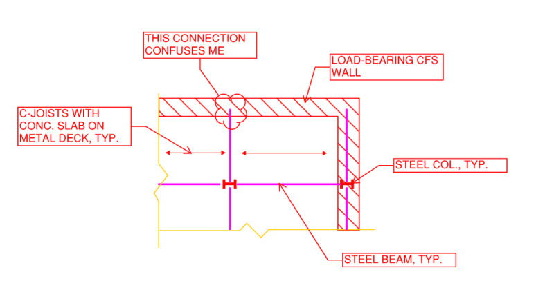
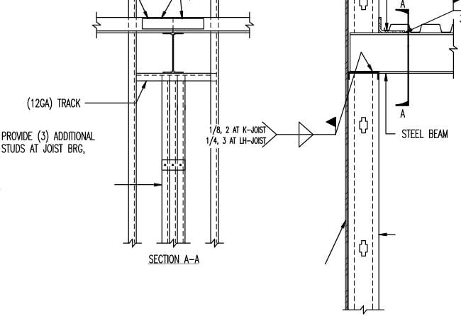
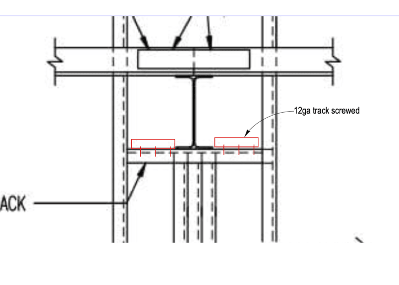
Does anyone have connection details of the I-beam supported by the load-bearing CFS wall?

The end reaction is very minimal in this case. My initial thought is to have a built-up post using 3 or 4 studs, a top plate over the post and welded to the post, I beam on top of the top plate with 4 bolts.

The wall and beam are perpendicular to each other if that makes the difference.
 
Replies continue below

Recommended for you

I've only ever used HSS post in this scenario. Its not that you can't use CFS but the connection is something I've wanted to stay away from. Perhaps CFSEI has a detail for this that you could consider. Link.
 
driftLimiter,

driftLimiter said:
something I've wanted to stay away from
I have been avoiding the steel to cfs wall connection until now. But the client is pretty adamant about keeping them all cfs studs.
Thanks for the reference.

I will try to convince him again and see how that goes.
 
XR250,

The beam is connected to the column at one end, and the other end is sitting on top of the load-bearing cfs wall. Please see the sketch below.

SKETCH_gaijos.png


I was also wondering if I could get away with replacing this beam with a double c box girder and consider the column restrained at that level.
 
XR250 said:
Same question - why do you need an attachment
This is a 4-story building with a penthouse, I have to limit the unbraced length of the column at its weak axis.

dold said:
This is what we do for fairly lightly loaded beams.
Thanks! This is close to what I imagined. Any reason you use welds at the bottom flange with a track instead of bolts with a plate? Money?
 
A typical bearing plate would have the W section fillet welded to it... likely more reliable that trying to put a bolt through the flange.

-----*****-----
So strange to see the singularity approaching while the entire planet is rapidly turning into a hellscape. -John Coates

-Dik
 
I like dold's detail in general, but it looks to me like it lacks torsional restraint of the beam that AISC requires. I would also bolt to the track below. Welding light gauge to light gauge is hard enough...welding light gauge to structural steel takes a wizard. They're out there, but tough to find and it's difficult to clean up after the pretenders.
 
I'm a fan of positively attaching things - for erection stability if nothing else. After all, OSHA does require 2 bolts for solid web members prior to releasing the hoisting line.

I'm also not sure I'd trust light gauge blocking to provide torsional restraint. I'd prefer an end plate or web stiffeners welded to the beam in the shop (end plate has the advantage of not getting in the way of bolting to the track in the wall).

 
I would def. spec web stiffeners. I have no problem with light gage blocking. Honestly, friction will provide the torsional restraint. If there is no friction, there is no load.
If you look at Dold's detail, they are counting on weak axis bending of the "King" studs to provide the restraint - which is also questionable.
 
Thanks all for the great input!

phamENG said:
I'm a fan of positively attaching things - for erection stability if nothing else
This is very me! Especially this is a residential project and I want things to be in their place.
 
Design it for the load and if necessary add a 1/8" to 3/8" material as required. I'd typically just add a 1/8" or so and check it... maybe 1/3 the load applied to a 'plate' 1-1/2"x6" size that is fixed along the edges using Roark or some other means. It may be that 14 or 12 ga, works.

-----*****-----
So strange to see the singularity approaching while the entire planet is rapidly turning into a hellscape. -John Coates

-Dik
 
Re: torsional restraint. I omitted part of the detail for anonymity's sake, but the deck edge angle is welded to the top flange (so is the deck technically). And again, this is for really lightly loaded beams (W8/10/12ish) with a reaction similar to that of a bar joist - couple thousand pounds at most. It's actually the exact same detail we use for bar joist bearing on a balloon framed wall but with a WF drawn in. I'm sure part of the argument for further restraint would involve the wall sheathing (typically steel sheet in our case) being screwed to all of the CFS members, including the "bearing track". For any beam other than a light roof 'joist' type deal I'd look at web stiffeners. Since OP's beams are supporting a floor I'd probably throw in stiffeners.

As far as the welding goes...yeah, I see the hesitation with welding to CFS. But I don't see a good way of bolting the beam to that track with the triple stud right below it. Unless you weld the beam to a bearing plate then bolt the bearing plate to the bearing track. Just seems like a lot of extra pieces for no real benefit. We've never had issues with welding to heavier gauge stuff. Anything lighter than 12GA is a little iffy.

 
Status
Not open for further replies.
Back
Top