Continue to Site

Eng-Tips is the largest engineering community on the Internet

Intelligent Work Forums for Engineering Professionals

  • Congratulations waross on being selected by the Eng-Tips community for having the most helpful posts in the forums last week. Way to Go!

steel beams for thick wall. 1

Status
Not open for further replies.

Wilko78

Structural
Apr 20, 2016
11
Hi there,

I'm based in uk and have done some calculations to size beams to replace a load bearing stone wall

Wall thickness is 530mm so approx 500mm stone/mortar wall excluding render.

I have sized 2 off 203x203x 46 uc beams. This only comes to 406mm total width.

I'm not sure whether I should specify 250mm wide top plates for each beam (totalling 500mm) to ensure full contact between wall and beams. Or whether the 100mm overhang (spread over 33mm either side of each beam) is acceptable. I can find no guidance in specifications for this.

Would I be able to use a top plate if I could get away with 2 times smaller 153uc beams, as these would be much narrower.....

Any thoughts? apologies if this is a simple one, but I cant find the solution in any of my books or online.

Thanks in advance.
 
Replies continue below

Recommended for you

I'm sure that a 33mm overhang isn't a problem. That said, won't you want a plate or something anyhow to encourage the two beams to act as a unit? I agree that the beam size seems suspiciously small given the stringent deflection requirements that would normally accompany such a scenario.

I like to debate structural engineering theory -- a lot. If I challenge you on something, know that I'm doing so because I respect your opinion enough to either change it or adopt it.
 
Hi There,

thank you for the feedback.

The loads are relatively light as the wall is a first floor wall with only a roof gable and roof loads above. the clear span is 5.5m.

I have been conservative with the loadings and have sized based on a single beam supporting the load.

I'm just not sure if i should stipulate that top plates are welded to provide continuous surface contact between wall and beams. The stones in walls are large so I believe I can do without but am just seeing if there are other opinions.


Wilko78 said:
Apologies if this is a simple one...

There is more to this project than you are assuming. I suggest you consult your boss or mentor before proceeding.

Deflection of beams supporting masonry is critical. The beams you have selected have a span to depth ratio of 27-to-1 (5500 mm / 203 mm). Without doing any calculations I can assure you that they are not suitable for this application.

Also, side-to-side beam stability needs serious consideration. A plate or two on top of the beams is not enough.

If you want to get into the numbers here, we can do that... or not. What is the calculated beam deflection at full load?

[idea]
[r2d2]
 
Many thanks!!

I didnt check the basics before I proceeded. The depth/span ration is out and because of my not checking I overlooked an error in my calculations. I have a 20mm deflection which is too much. I originally read the 20mm as 2mm and thought nothing more of it.

I may be able to use a 254 UC beam as this falls within the band of depth/span ratio, but could opt for a deeper UB depending on how I get on with deflection.

If beam ends up being narrower than wall, my original question still stands, should I recommend a plate to provide a continuous surface or can I assume (as i believe is correct) that a small gap is acceptable either side of beam.

Thanks


Hmm, a top plate tying the two beams together would certainly make a nice lateral bracing system for such a heavy load. Any rotation or kick out would be covered in addition to providing a nice grouting surface to get the contact between the beam and stone wall.

Are you going to preload the beams somehow so that the initial deflection doesn't produce the typical diagonal portal cracks?
 
Wilko78 - Glad you found the error. The (US) Brick Industry Association has a technical note on Structural Steel Lintels. It is good advice for any masonry project. They recommend limiting deflection to L / 600 or 8 mm (maximum).

Since we don't know the loads, I can't comment too much on beam selection size. However, I disagree with what seems to be your priority - maximum flange width. IMHO, it is better to select beam size based on web depth, without regard for flange width - to limit deflection as much as practical. Place the beams so that there is no overhang at all. Span the gap and cover the top of both beam flanges with a 500 mm wide steel plate of suitable thickness. Weld the plate to both beams. Providing maximum spacing between beams will help with resisting any eccentric loading on the wall.

Limiting deflection is important, per the technical note. But it will also help load sharing between the two beams. Any differential loading on one beam creates a magnified problem. As load on one beam increases, load on the other may decrease. The result, as one beam's deflection increases, the other beam's deflection decreases, causing wall tilt be twice what would otherwise be expected.

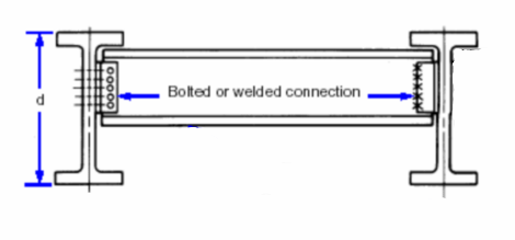
Another step I would use is to tie the two beams together with a few diaphragms (say 3 or 4).

Diaphragm_gjxgov.png


[idea]
[r2d2]
 
We've been through this before. Check out this thread: Link. Be sure to review the attached sketches as well.

I like to debate structural engineering theory -- a lot. If I challenge you on something, know that I'm doing so because I respect your opinion enough to either change it or adopt it.
 
I disagree a bit.

1) I don't think that there will be space between the beams to install meaningful rollover beams as diaphragms without contructability issues. I think the top/bottom plate concept from the other thread is the way to go.

2) I think that some degree of overhang is actually desirable as it will allpw for some field tolerance in the positioning of the beams.

I like to debate structural engineering theory -- a lot. If I challenge you on something, know that I'm doing so because I respect your opinion enough to either change it or adopt it.
 
KootK

1) No need to debate this question... all the OP has to do is tell us what size and spacing will be used for the beams, and the constructability issue will be self evident. My advice should improve constructability:

SlideRuleEra said:
I disagree with what seems to be your priority - maximum flange width. IMHO, it is better to select beam size based on web depth, without regard for flange width - to limit deflection as much as practical.

2)
Wilko78 said:
Wall thickness is 530 mm
Using a nominal 500 mm width, with no overhang, looks like plenty of field tolerance for beam positioning to me.

[idea]
[r2d2]
 
SRE said:
1) No need to debate this question... all the OP has to do is tell us what size and spacing will be used for the beams, and the constructability issue will be self evident. My advice should improve constructability:

I'm just waiting for OP to post the revised beam size that I can draw the detail my own self...

SRE said:
Using a nominal 500 mm width, with no overhang, looks like plenty of field tolerance for beam positioning to me.

We must be talking about different things. I see a 500 plate below a 500 wall as having no lateral tolerance whatsoever.

This condition always seems to come up with European folks. I've never actually used the system myself. Anyone able to enlighten me with regard to the sequence of construction, shoring, etc?

I like to debate structural engineering theory -- a lot. If I challenge you on something, know that I'm doing so because I respect your opinion enough to either change it or adopt it.
 
Hi all,

I really appreciate the feedback. I'll let you know steel sizes and see if that changes anyone opinion tomorrow.

I saw the sketch linked of small top plates at intervals and beams on out edges. (thanks) imteresting idea. I'll get back to you tomorrow. Cheers
 
KootK said:
We must be talking about different things. I see a 500 plate below a 500 wall as having no lateral tolerance whatsoever.

Crap. Just realized that the wall may actually be 530 and, thus, there is some tolerance after all. My bad.

I like to debate structural engineering theory -- a lot. If I challenge you on something, know that I'm doing so because I respect your opinion enough to either change it or adopt it.
 
Wilko78 - When you select the new beam size keep in mind that you are not designing for moment, but for deflection under code-required maximum load combination:
L /688 (8 mm deflection over 5.5 meter span).

The moment in any beam size that meets that deflection criteria will be so low (compared to the beam's maximum capacity) that LTB will probably not be an issue for a 5.5 meter span.

[idea]
[r2d2]
 
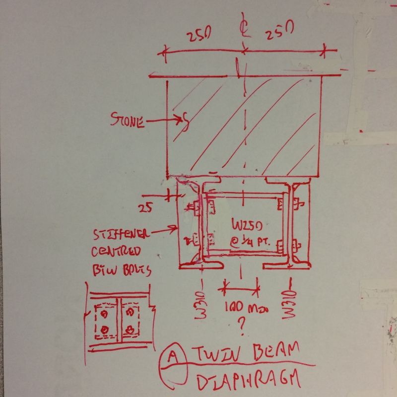
Even if LTB concerns are minimal, I like the idea of having diaphragms for two reason. Firstly, some ability to share unevenly applied load is good. Secondly, these narrow beams don't always have the greatest rotational restraint at the ends, depending on how their "built in". The sketch below is my proposal for a contructable diaphragm.

image_pc14bw.jpg


I like to debate structural engineering theory -- a lot. If I challenge you on something, know that I'm doing so because I respect your opinion enough to either change it or adopt it.
 
Hi all,

so I have selected a 356x171x57 UB

this supports the full load independently, so doubling up the beams provides alot of redundancy and covers the TIF factor (Things I forgot).

it meets the L/360 requirements for Eurocodes (for beams carrying plaster) so I think the deflection is OK (limit is 15mm and I get 15mm)

Where does the L/688 come from?

As for the installation i like the idea of the stiffeners. Not sure how practical they will be to install.

As for top plate, with such narrow beams I think i need to suggest them. it will definitely be needed if the stone wall has loose infill (only determined when work starts). ....
 
Wilko78 said:
As for the installation i like the idea of the stiffeners. Not sure how practical they will be to install.

I don't know either. As I mentioned above, I could use some help understanding the sequence of construction.

-Would one assemble both beams on the ground and install them together?

-Does one beam get cut into place and the second beam comes later?

-Will there be a temporary shoring system of some sort?

-Will the beams bear on a pocket in the stone at the ends or is there a new column of sorts at the sides of the opening?

-Will you be attempting to grout between the stone and the steel to achieve a more uniform bearing?

-Will there be a door or window tying into the underside of the beam?

Wilko78 said:
it meets the L/360 requirements for Eurocodes (for beams carrying plaster) so I think the deflection is OK

The deflection issue is about preventing damage to the very stiff, very brittle stone. Plaster limits won't govern.


I like to debate structural engineering theory -- a lot. If I challenge you on something, know that I'm doing so because I respect your opinion enough to either change it or adopt it.
 
Status
Not open for further replies.

Part and Inventory Search

Sponsor