Eng-Tips is the largest engineering community on the Internet

Intelligent Work Forums for Engineering Professionals

  • Congratulations waross on being selected by the Tek-Tips community for having the most helpful posts in the forums last week. Way to Go!

Steel box Frame examples and benefits over goal post and offset foundations

Status
Not open for further replies.

liam1369

Structural
Nov 13, 2014
73
0
0
GB
Hi All,

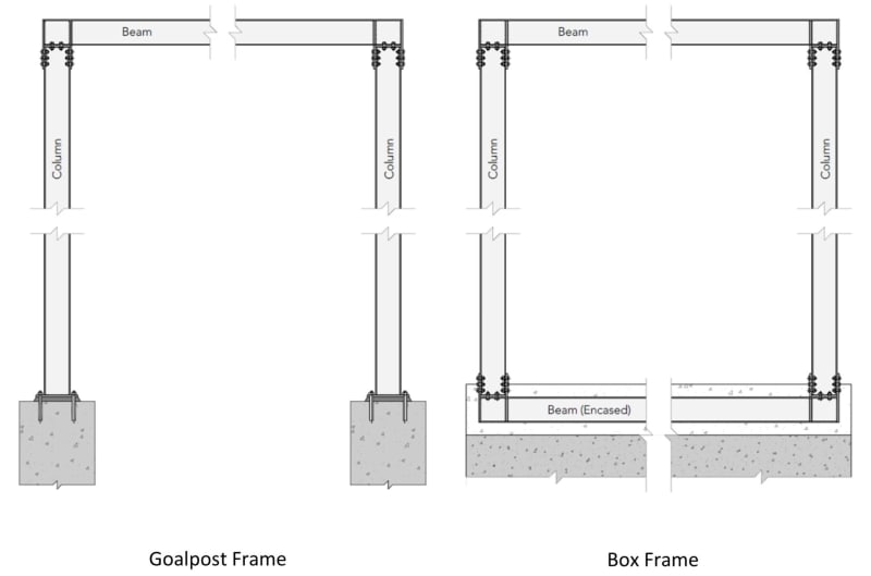
Does anyone have any literature or design examples on steel moment box frames to allow for large openings in rear walls (typically). I am struggling to find any examples or design guidance online or in any steel design books.

In addition, can anyone explain in Simple terms when they are more suitable for use?

Is it simply when offset pad foundations for goalpost moment frame exceed bearing capacity?

I know it makes life easier as you can effectively use the same foundation by encasing the bottom beam slightly above.

Kind regards,

Liam
 
Replies continue below

Recommended for you

Can you post a sketch of what you are trying to do? "box frame"....is this a 2D or 3D frame? "Goal post moment frame"....what does this arrangement look like (a single post "goal post"? a double post "goal post"?, something else?). Offset pad foundations....offset vertically? horizontally? both? Encasing the bottom beam....so there are multiple levels to the moment frame?
 
Are we talking about a steel beam at grade here? We need sketches. There is a lot of resources available for conventional moment frame design, if you have something a bit different then you may need to adapt what resources are out there.

 
5530C909-7BF1-4176-856E-DD88ED72ABD8_mnql89.jpg
 
Yes, so the thing to understand about moment frames is that they are one of the more flexible lateral systems. Inasmuch you will need to closely look at drift, and if in the US in SDC D or greater, the drift limit for moment frames is adjusted to be more stringent than other lateral systems (based on redundancy).

In my experience, heavy seismic loads lead to large drifts in moment frames, and much of the time the selection of the beams and columns is not for strength but for stiffness (drift) control.

So the goalpost frame is the first and obvious choice because it has fewer parts, the base is pinned which makes it pretty simple to install and analyze. However this configuration might not lead to very economical sections, and it might be sized so large that it doesn't fit into the space.

This is where the box frame can help, by have a moment connected beam at the base level, columns get the benefit of the flexural rigidity of this beam and rather than a freely rotating pin at the base, we have another moment joint.

Box frames can have a significant effect on the drift compared to a goalpost frame if all else remains the same. I usually still consider a pinned base at the bottom of the columns, but in the model you add the grade beam rigidly at that joint. I don't like that the picture doesn't show any discrete column anchorage, I suppose its possible to found the columns right on the embedded beam but I don't like it, hard to analyze how the forces get into the concrete this way.

The downside of box frames is in the additional material (maybe less weight overall though), foundation preparation, reinforcement, etc. As with everything in engineering we have to use judgement to decide what is the optimal solution.

My general process for moment frames is to design them for strength, then check drift, then start sizing everything up to meet the drift requirement. If you have some archtiectural constraints on the size of the columns and the beams that is a good place to start.
 
Hi drift,

Thanks for the detailed explanation.

The bottom beam of the box frame is typically 'encased' in concrete due to being below ground and will then bear against the existing foundation.

As per my OP, do you have any reference to an actual design exemplar?

Liam
 
In principle the design of a box frame is the same as the goal post frame, get your lateral force, determine the internal forces in the frame, design accordingly, check deflection.

I've never seen an example of this specifically unfortunately. That is one of the reasons I would use a slightly different configuration, The transfer of forces is easier to understand and justify at a baseplate. The encased beam is just there to add rigidity to the base reaction. Design anchorage for shear and uplift just like the goal post frame.

 
Status
Not open for further replies.
Back
Top