Eng-Tips is the largest engineering community on the Internet

Intelligent Work Forums for Engineering Professionals

Steel cable length measurement 1

Status
Not open for further replies.

Ingenuity

Structural
May 17, 2001
2,347
0
36
US
I live/work in the structural 'world' and need some assistance from EE's.

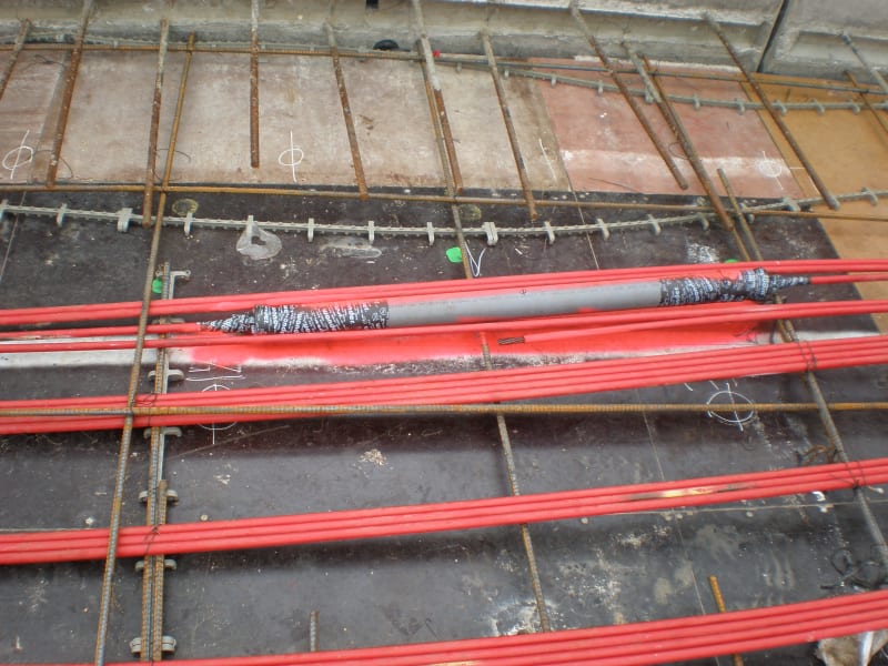
I work with unbonded post-tensioning strand tendons - basically high-tensile 7-wire carbon steel strands that are 'insulated' with HDPE sheath along there continuous length, and placed inside concrete slabs and beams and stressed to 80% of their tensile strength.

Sometimes (often?) these strands get severed (drill holes, core machine etc) and fracture. Often the party that did the drilling does not report the incident or was not aware (?) and then a few days later somebody notices the end of the strand has exited the slab edge.

cable_qv4few.png


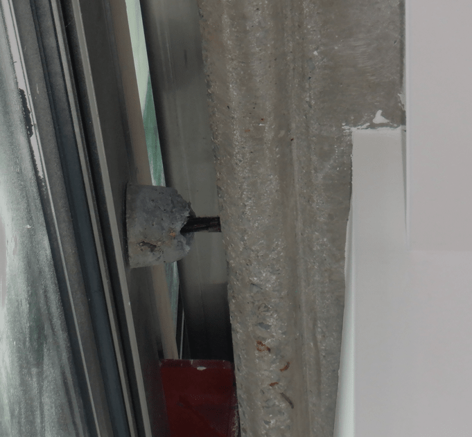
We are often tasked with determining the location of the break and probable cause, and eventual repair. Probable cause requires us to know the location of the break, and on a construction project site this can be challenging with HVAC/mech/elec sub on a project to determine whos fasteners/hole is to blame.

We usually resort to extracting the failed strand segment, then simply measure the extracted length and determine the failure location. But often this is very inconvenient (like the exterior of the 40th floor of a building).

There exists electrical equipment to determine electrical cable length measurement and 'shorts' using TDR. Would such devices work with 7-wire solid carbon steel strands, where access to only one end of the cable is available?

I am looking for precision/accuracy of say +/-1 foot.

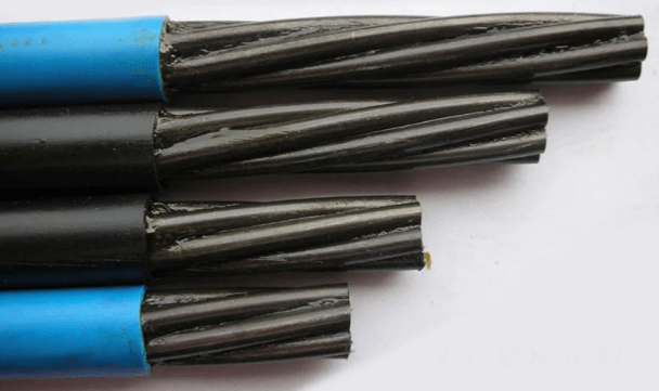
A typical 7-wire strand is the following:

strand_pspooa.png


Thank you.
 
Replies continue below

Recommended for you

Access to one end is necessary and sufficient. Propagation velocity is a function of electrical properties, but over building distances the difference between .97c and .975c probably leaves you within your +/- 1 foot tolerance (but becomes a huge problem for lines many 10's of miles long). If you have a bunch and all but one have one reflection time and one has a lower reflection time you can figure the propagation time and then calibrate for the distance to short time reflection. A partially damaged, but not fully severed, cable will be trickier.

I’ll see your silver lining and raise you two black clouds. - Protection Operations
 
Thanks David.

All my building situations of these types of strand failures are short (less than 300 feet MAX, and typically more like 100 foot or less). When failure occurs where the slab edge exposes the strand then ALL 7 wires have failed so a partially damaged strand is not part of our detection.

The .97c and .975c numbers you state are they the velocity factors (VF or VoP) you would expect for solid 7-wire strand of 1/2" nominal diameter, or were you just stating relative numbers?
 
Never tried to figure out single conductors in "conduit". But for transmission lines (wires hanging in air), the propagation velocity is slightly below the speed of light, 'c'. Actually, lines in conduit can have a much lower propagation velocity, down to even 0.6c) Always have to look it up to make sure but I think it's something like root(L/C) that determines the velocity of a line. Don't know how that translates into a single conductor. But if you can bracket the suspect cable with a couple of supposed good cables (if they both have the same time you should be good, the more the merrier) you know the real time. At 'c' the propagation velocity is around a nanosecond per foot. If you have a 50' slab, do you also have the instrumentation to measure the difference between 0.1μs and something slightly less? Being able to get to both ends would help, one will show much more variation from the controls for a failure near one end.

I’ll see your silver lining and raise you two black clouds. - Protection Operations
 
Yep. Based on what I know of what's now available as Traveling Wave relays. Fault sends out signals at the propagation velocity to the ends and there are reflections off the ends. Time becomes distance, but a good reference is essential. In the case at hand, undamaged cables become the ideal reference.

I’ll see your silver lining and raise you two black clouds. - Protection Operations
 
Yes, I have numerous undamaged strands that I can 'calibrate', with known length. The strands are manufactured 6,000 + linear feet reeless coils, so I plan to check say 25', 50' 75' and 100' test lengths.

Thanks for your assistance.
 
Laying out straight will have a different propagation velocity than coiled up.

I’ll see your silver lining and raise you two black clouds. - Protection Operations
 
Ok, thanks.

The steel 7-wire strand is coated with a corrosion-inhibiting grease then a HDPE sheath is formed around the assembly as part of the manufacturing process. I guess the grease will affect the velocity too?
 
I doubt the grease would. But the inductance of the conductor does factor in and when coiled the inductance is different than it is when laid out in a straight line.

I’ll see your silver lining and raise you two black clouds. - Protection Operations
 
I agree with IRstuff, the cable surrounded by concrete is likely to have a different capacitance which also affect the propagation velocity.

If you can't access a real in-situ, perhaps you can box pour a section and compare it to an unboxed section to compare the per-unit difference.
 
Yes, I shall be field-testing/calibrating strands installed in concrete slabs too.

The HDPE sheath is typically 50 mils (2mm) thick, so am I correct to assume this will provide sufficient insulating properties that adjacent strands (with intimate sheath contact) will not come into play?
 
I wouldn't be concerned about conductivity between the adjacent strands. But it will affect the capacitance.

Are the adjacent strands how they are installed in-situ or are they a mock-up for test calibration purposes?
 
JezNZ:

In-situ they are installed as per this typical photo:

PC170020_z73eyp.jpg


Typically from 2 to 5 in a flat bundle for slabs, and often 7 in a bunched-up bundle in beams.

For known length in-situ strand tendons I shall be conducting a comparison/calibration test/s to check the accuracy of length measurement.
 
I see you will likely find different results based on number of cables in bundle and the position in the bundle of the cable under test.

How significant the difference, I cannot say, perhaps someone with more experience can weigh in.

Either way, worth considering recording the number of cables in the group under test and the position of the cable in the group when you conduct your testing.


Out of curiosity, what is the grey pipe looking thing? Is that a cable-joint? And if so are they common? Reason I ask is the principle of travelling wave reflections is that you will get a reflection back from each step-change in impedance (akin to each physical change), so you will get a 'false positive' for things like cable joints.
 
Since it's a non-termination condition, effectively turning the cable into an antenna, is there a way to detect the EMF spike in amplitude at the place the impedance changes where the break occurs?
 
Thank you for your comments.

JezNZ said:
Out of curiosity, what is the grey pipe looking thing? Is that a cable-joint? And if so are they common? Reason I ask is the principle of travelling wave reflections is that you will get a reflection back from each step-change in impedance (akin to each physical change), so you will get a 'false positive' for things like cable joints.

The grey pipe is indeed a splice. These are not very common, and occur when the strand is accidentally damaged (cut wires etc) during construction and they place a splice chuck inside a greased PVC tube and seal. For such a case we would NOT be proposing this TDR method to determine any cable length measurements.

Just curious, would an oscilloscope be able to pick up splice location/s such as that in the photo above? I would guess it would show up as a bump on the scope, so may be able to back calculate the approx position of the splice.


Status
Not open for further replies.
Back
Top