Eng-Tips is the largest engineering community on the Internet

Intelligent Work Forums for Engineering Professionals

Steel Decking over CHS beam 1

Status
Not open for further replies.

Italo01

Structural
Sep 4, 2021
169
0
0
BR
Hello,

I'd like to your opinions about tubes used as composite beams. I have the situation of a bridge composed of tubes, both columns and beams, which is partially built. It is a small bridge and it was designed initially to have timber slab over the steel tubes but the company that was building had some problems and the city ended the contract. Now, the city wants to finished the bridge using Steel Decking.

I was hired to analyze this new solution, since the concrete will impose new loads on the structure. The structure is fine with the new loads, since the composite action will increase the stiffness and strength of the beams and since the columns have additional capacity for the loads. My question is about the connection between the deck and the Tubes. Is there a problem in supporting the deck over a tube due to the small area of contact?

Thank you in advance.
 
Replies continue below

Recommended for you

Ital01 said:
Is there a problem in supporting the deck over a tube due to the small area of contact?

I think that would be a problem. Without a nominal "flat" to work with:

1) You run the risk of web crippling in the deck while the concrete is wet.

2) Fastening to to the CHS will be kind of a nightmare.

3) The finished condition may not do a great job of LTB bracing the CHS.

...

Can you weld some WT shapes on top of the CHS perhaps? Or angles to the upper, inside quadrant?
 
Maybe i can weld the angles but i think that this cost will be very huge. When i said that the bridge is small, i wasn`t clear but i was refering to the width, which is 4m. The length is 84m and i have 5 tubes, I also have transverse tubes, so this would total 6000m of angles to weld.
 
Kootk, i was worried exactly about the web crippling ofthe web.

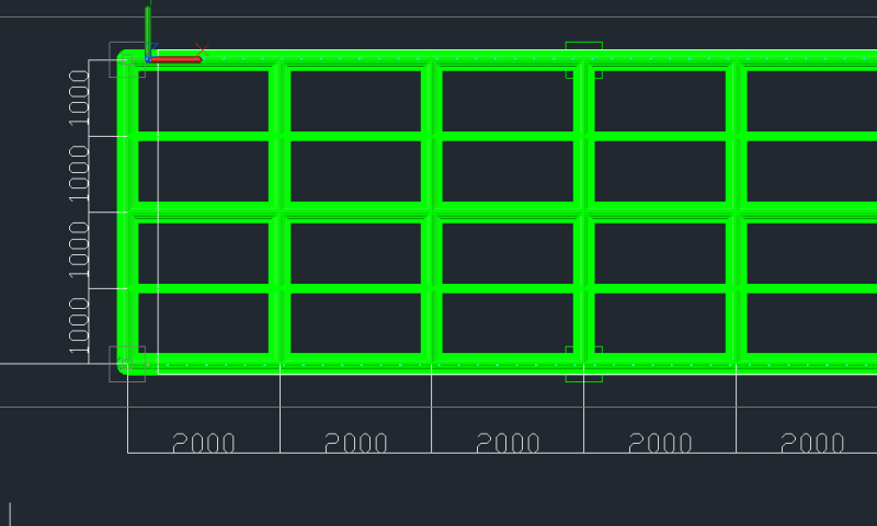
The LTB bracing of the CHS isn`t concerning since i have a very dense grid of beams, as shown in the image below.

Bridge_Grid_exlhv3.png


The columns are Pipes 10" SCH40, spaced ath 6000mm, all the beams are also Pipes 10" SCH 40.

PS: I think the nomenclature tube which i used previously is incorrect, isn't?
 
How are you mitigating the potential for rusty deck syndrome on this significant chunk of outdoor infrastructure? That's almost more of a concern for me than the CHS connection.
 
Sorry for the late response, Kootk.

This small bridge is located in a rural area and in a semi-arid region. I thought first at specifying waterproofing to the concrete, a drainage system so the water does not accumulate and a maintanence plan to the decking.
But your question did bother me and i'm worried that this solution proposed can be very problematic. I don't think that a small city will comply with the maintenance plan, especially when a new administration take over.
Since they don't want the timber slab anymore and the beam spacing is so low(1 meter), i think that a slab of reinforced concrete with timber formwork will be the best solution.
 
Italo01 said:
Sorry for the late response, Kootk.

No sweat. We're on your schedule here.

Italo01 said:
..i think that a slab of reinforced concrete with timber formwork will be the best solution.

I was thinking same. That said, even that's a bit weird from a connection detailing perspective. Less weird, but still weird.

Do we know how the original, timber deck was intended to be fastened to these circular tubes?

 
I don't know. They provided me with very simple design drawings which don't show these details and the worst is that i visited the partially built bridge and a lot of things are different from the drawings.
 
This is an interesting and goofy structure. If I'm interpreting everything correctly this looks like a summer intern project gone wrong! My first concern is for the web crippling of the metal deck panels due top lack of bearing area.

The grid of pipes is already fully constructed and now you need to add a deck to it?
What size are the longitudinal and transverse pipes?
Do you know their current finish?
What is the design live load for this structure, something similar to AASHTO H5 or H10?
 
Status
Not open for further replies.
Back
Top