Hello all,
I am trying to model a steel frame with a wood shear wall which seems like an easy enough task. The columns are pinned at the base and the beam is simply supported. When the shearwall fills the entire frame everything is dandy. When the shearwall only fills a portion of the frame Risa reports instabilities and locks two nodes. Any suggestions? Note that all steel elements are "physical members".
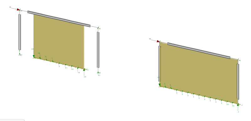
The frame to the left results in the top rght and lower left nodes getting locked. The one on the right is fine.
I am trying to model a steel frame with a wood shear wall which seems like an easy enough task. The columns are pinned at the base and the beam is simply supported. When the shearwall fills the entire frame everything is dandy. When the shearwall only fills a portion of the frame Risa reports instabilities and locks two nodes. Any suggestions? Note that all steel elements are "physical members".
The frame to the left results in the top rght and lower left nodes getting locked. The one on the right is fine.