Eng-Tips is the largest engineering community on the Internet

Intelligent Work Forums for Engineering Professionals

Steel Girders Damaged during deck removal (Saw Cutting) 1

Status
Not open for further replies.

OLDSOUL22

Structural
Oct 6, 2021
32
0
0
US
Hello Everyone,

Last week the contractor started demoing a concrete deck on a single span bridge to be replaced with a new deck. The approved demolition procedure stated to saw cut the deck at the longitudinally at the center line of the girders and every 5ft transversely (approx. 7'x5' pieces) then remove it with an excavator with a thumb attachment. the original deck thickness is 8" (varies with concrete delamination 6" to 8"), as a precaution we agreed on setting the saw depth (4" to 5") to avoid any unintentional scarring of the girders. but they still managed to scare and dent the girders really bad. at some locations they cut through the full thickness of the cover plate and the 2 back to back angles that forms the flange.
Attached is some pictures of the damages.

I'm trying to fix the damages with the least amount of work to prevent any delay, any suggestion is highly appreciated.

Thank you all for always being very helpful and I wish I can help the same way one day.

(DrZoidberWoop) thank you for you reply on the original post, I deleted it for the reason you mentioned.


Sr. Project Engineer
MSc in Civil Engineering
 
Replies continue below

Recommended for you

It seems like you should be able to come up some weld procedures which can be used to restore the capacity of the cut steel. This will require fastidious joint prep, backer plates and the like.
 
My first thought would be to make the cut into a V-groove or enlarge the cut to form a butt joint. Then fill the gap with a weld, like maybe a CJP type of weld. Not sure if that would create fatigue issues or how weldable that steel is since it looks riveted.
 
OLDSOUL22 said:
...concrete deck on a single span bridge to be replaced...

So the damaged flange is always in compression:

Test samples of the existing steel to get it's structural properties and determine if it can be welded.

Using the above information, revise design of the deck to make it composite with the beams (and take over the job of the beams' damaged compression flange).
If the existing steel can be welded, use welded shear studs.
If the existing steel can not be welded, drill the cut flange and use bolted shear studs like these or bolts with the heads projecting upward.

 
The longitudinal cuts don't bother me much. I would fill them with weld. The same for shallow transverse cuts.

At the transverse cuts through the girder flange and angles, welding may be an easier repair than bolting a plate although there's a lot of prep work involved. As SRE said, if you plan to weld test the steel especially if it's A7, which didn't have a specified chemistry. You could go with bolting a splice plate. However, there are several considerations:

Some owners require cheese plates over the rivets then the repair plate. The rivets are drilled out and replaced one by one, but drilling rivets is slow and it uses a lot of bits. Depending on the haunch depth, the plates could eat into the deck. Then there's cutting of any stiffeners to install the bottom splice plate. You could use a thick plate to avoid adding a plate below the flange but it could eat into the deck.

One way to avoid cheese plates would be to use individual repair plates along each rivet line; bust out the rivets along one line, add the plate, repeat until done.
 
JLNJ :
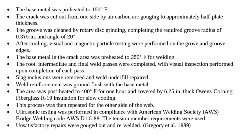
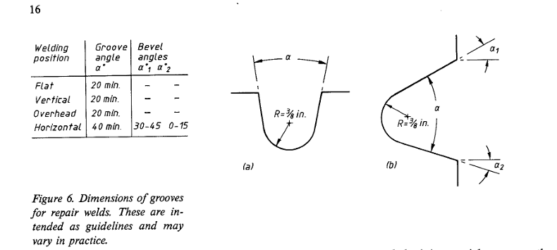
For cuts less than 1/8" I was thinking of following the cracks repair procedure outlined in "Welded Repair of Cracks in Steel Bridge Members (Gregory et al. 1989)", prep the cut as shown in the picture, and follow the procedure. However, I do not feel confident doing the same for deeper cuts.(where the cover plate is cut (40% to 100%))
Capture_xajawy.png

Capture_klewux.png


MotorCity:
I have no idea what grade is the steel, there is no original drawings available, but It looks like there has been some welded repairs done to the bridge at some point. I am not too concerned about the fatigue since we are in compression zone.

SWComposites:
he is, and he is being charged with the engineering cost too.

SRE:
I never thought about this, will look into it. Thank you for the out of the box thinking!

bridgebuster:
Even with full depth cuts? will you still fill them with weld?
Would you recommend testing the steel although there has been some welding done to the bridge at one point?
How do you feel about doing CJP for the transverse cuts?
We only have 1/2" haunch from the top of the angles, so basically no haunch where we have cover plate. I can add some thickness to the deck to cover for the losses by the splice plate but that ultimetly would increase the dead load.

Thank you!


Sr. Project Engineer
MSc in Civil Engineering
 

May not be good... a few years back I was going to renovate some rivetted bridge cranes for a local railyard... first thing I did was have coupons taken to test the steel... it had high sulphur content and couldn't be welded. Project stopped; I don't know whatever happened to it.

So strange to see the singularity approaching while the entire planet is rapidly turning into a hellscape. -John Coates

-Dik
 
Even with full depth cuts? will you still fill them with weld? Based on the photos, I thought the longitudinal cuts were shallow. If the longitudinal cuts are completely through the plate, my gut feeling is leave it but drill a 1" diameter hole at each end of the cut to get a nice stress distribution around the cut.

Would you recommend testing the steel although there has been some welding done to the bridge at one point? It's probably a good sign that the steel is weldable. I would take a look at the welds just to make sure there's no sign of cracking.

How do you feel about doing CJP for the transverse cuts?That was my thought CJP
 
I agree with JStructsteel. Make the contractor submit a repair strategy. The last time we had that happen (Yes, we've had it happen several times), after several rejected attempts at a mitigation strategy, the solution we eventually approved involved, grinding out (tapering the edges at a 1:12) the shallow cuts, adding bolted cover plates at the deep cuts, and adding shear studs the full length of all the girders to make it a fully composite superstructure. I would leave it to the contractor to design the mitigation strategy, but drop some strong hints that they're going to need to make it composite for you to accept it.

My advice is make it as painful and expensive as you think you can, so they are more careful next time. We made the mistake of trying to be reasonable and work with the contractor to find an economical solution the first time they did it, and apparently that was a mistake, 'cause 6 months later, we doing it all over again on another bridge.

Rod Smith, P.E., The artist formerly known as HotRod10
 

We are anticipating a big new contract from the contractor so let's say I was trying to maintain a good relationship by helping him with the engineering. Eventually, I had to ask them to do the repair procedure and submit it for my approval for time constraints. Now, I'm waiting for the revised drawings.

Thank you all for your input! I'll keep you posted. [smile]
 
For the transverse cuts through the existing cover plate, the contractor engineer is suggesting removing a 2' section of the cover plate, CJP weld the flange angles, then replacing the cover plate with a new 2' bolted through the rivet holes and a CJP weld to the existing cover plate on both sides. they submitted the supporting calculation for the temporary removal of the cover plate.
To be able to perform CJP for the cover plate they are suggesting using the existing flange (angles) as backing for the joint and a single groove joint, I'm not sure how I feel about this and I couldn't find any source that support or prohibit the use of existing steel as backing. Any ideas where I can learn more about the subject?
Thank you,


MSc in Structural Engineering, PE
 
Thank you for the references! much appreciated.
I read through the AWS D1.5, welding reference manual, the Structural Magazine article and I'm currently reading through Ricker's paper. very useful information. However, no mentioning of using existing steel as a backer in any of them. Clearly in my case it does not meet the requirements for backing in terms of continuity, surface prep and the ability to be removed, but I figured that would frequently suggested and someone must have discussed it by now.


MSc in Structural Engineering, PE
 
OLDSOUL22 said:
To be able to perform CJP for the cover plate they (contractor's engineer) are suggesting using the existing flange (angles) as backing for the joint...

I'm not sure how I feel about this and I couldn't find any source that support or prohibit the use of existing steel as backing.

Well, quit looking. Throw this issue back to the contractor's engineer to provide you with necessary documentation.

I assume it is up to the contractor and his engineer to solve the entire problem with the bridge, not for you to "make" some half-baked repair procedure look acceptable.

 
Status
Not open for further replies.
Back
Top