Continue to Site

Eng-Tips is the largest engineering community on the Internet

Intelligent Work Forums for Engineering Professionals

  • Congratulations cowski on being selected by the Eng-Tips community for having the most helpful posts in the forums last week. Way to Go!

Steel OMRF Beam to Column Moment Connection query

Status
Not open for further replies.

NewbieInSE

Structural
Dec 19, 2019
234
Please see the following figure.
max._moment_the_system_can_handle_rtjfed.png


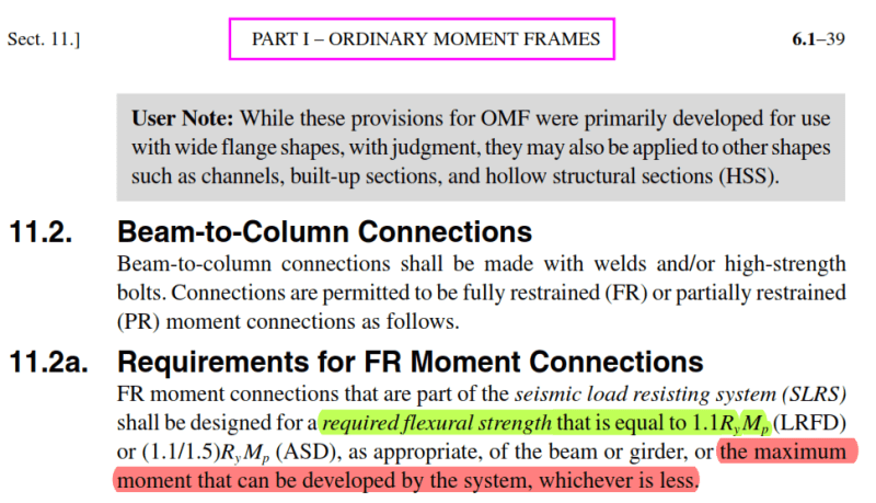
What is meant by "the maximum moment that can be developed by the system"? What I understood first is, it means the max moment which can be obtained using the code suggested load combinations. But instantly the second thought which comes in mind is "how can the bending moment obtained from code-based load combos be ever higher than 1.1RyMp?".
I know that code-based loads will be lower, then why say "whichever is lower?"?
Please help me understand. Thanks.
 
Replies continue below

Recommended for you

It means that some other part of the lateral system (e.g. foundation uplift) could act as a fuse and limit the moment that the connection is able to develop. See the Commentary for further explanation.
 
This is capacity design. Put aside the load combinations for a moment. The purpose of this is to ensure that, during an earthquake, the connection will not be the point of failure. Formation of a plastic hinge in the beam is far more ductile than the moment connection failing. So the moment connection has to be designed to resist more than it could ever see. Not more than we expect it to, but more that it is physically possible for it to see. Seismic design isn't about designing buildings to resist a particular force - it's about determining an approximate "external" force the roughly equates to actual internal energy from an earthquake that we think is about as bad as it will be but we don't really know. So the name of the game is creating fuses and failure points in predictable places so we can dissipate that energy and keep the building standing long enough to get people out (or maintain a hospital in operation for a while longer and then get people out).

So while the overall frame is designed based on the calculated seismic loads, individual components and connections are detailed based on these and other prescriptive requirements and/or load modifications (such as overstrength, redundancy, etc.).
 
"the maximum moment that can be developed by the system"?

For OMF's I believe this means that you can use the Overstrength Load Combinations (i.e. Omega * E) for the design forces / moments.
 
It doesn't necessarily mean that you use Overstrength Load Combinations. That is just one of the possibilities (along with column yielding, panel zone yielding, and foundation uplift) that is discussed in the commentary. In the case of Overstrength, you are designing the structure to remain essentially elastic, which obviates the need to design the connection for 1.1RyMp.
 
There is a type of frame like "frames with R=3.0 which are not specifically detailed for seismic resistance". Again we have OMF with R=3.5, So just for an increase of 0.5, members and connections need to go through excessive detailing requirements. Sometimes we can't use that 'Frame not detailed.....'

In the kind of structures we design, one or two storied steel structures, based on SDC, we are required to design using OMF, IMF, SMF etc. Seismic weight is too little too cause substantial hazards (in a shed, I don't see any loads except self weight).

I would be happy if 'the max moment that can be developed by system' meant load effects using overstrength factor for OMF.
 
Status
Not open for further replies.

Part and Inventory Search

Sponsor