Continue to Site

Eng-Tips is the largest engineering community on the Internet

Intelligent Work Forums for Engineering Professionals

  • Congratulations waross on being selected by the Eng-Tips community for having the most helpful posts in the forums last week. Way to Go!

Steel/PEMB Roof Bracing Question

Status
Not open for further replies.

JD P.E.

Mechanical
Oct 17, 2021
79
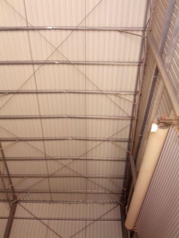
Let's say you have a middle bay braced on the roof (includes roof and side walls). I understand that the roof bracing is designed like a truss and the roof purlins nearest the rod/rafter connection act as the vertical members and the rods act as the diagonal members. I have 2 questions I need help to understand.

1) Is the roof bracing 'truss' usually just designed based on typical purlin spacing for the truss upright spacing, selecting some type of diagonal rod layout to make up the diagonals of the truss, and calc typical truss stresses based on wind/seismic?

2) Are the roof purlins (z or c shape) typically designed to be stiff enough to carry the compressive load to the braced bay? I see most roof designs on these buildings aren't designed to act as a diaphragm so that leaves the purlins.

 
 https://files.engineering.com/getfile.aspx?folder=81c1d2df-9799-4edf-bcc5-589fdb2ef622&file=1312620812_236628300_8-Pre-Engineered-Steel-Building-1-1.jpg
Replies continue below

Recommended for you

I don't really understand question 1. Question 2 would depending on the designer. I have seen the results of where the designer clearly did not design the purlins to be stiff enough to carry the compressive load. The entire end wall got blown in.

Personally I design specific compression members for lateral loads. In my locality this is the more common approach these days except for very small structures like domestic sheds.
 
Like human909, I am not a fan of using purlins as struts.
 
Okay, if you design compression only struts, what governs the spacing of them? Just personal choice and work out tributary force on each strut?
 
Yes. Usually that depends on locations of the wind columns, which in turn depends on the girts used.
 
I am not familiar with a wind column. What would set that apart from using eave compression struts to get wind forced to braced bays?
 
In an end wall, the horizontals (girts) which support the wall cladding span between vertical members, which I call wind columns. It makes sense to design the roof wind truss to directly support the reactions from those wind columns. If the truss is not in the end bay, struts can be used between the end wall and braced bay.
 
Not sure how the PEMB folks handle it, but in my line of work, we never include the purlins as part of the lateral force resisting system that utilizes a horizontal truss. Purlins are not in the same plane as a horizontal truss. If you have a diaphragm instead of a horizontal truss, the load path will pass through the purlins and into the lateral force resisting system.
 
The roof bracing will usually align with the endwall columns like hokie said, they're designed to take the wind load from the top of the columns. PEMB manufacturers will rely on the purlins on either side of the column to take the compressive strut loading, until the load becomes more than the purlins can take, in which case a specific cold-formed box or HR pipe member will be used as the strut.

Source: former PEMB engineer

Go Bucks!
 
I'm a PEMB guy.

1. The roof truss is based on the exact purlin layout on each particular building. PEMB is possible due to automating everything on computers so this is done automatically. X-bracing is usually tiered at endwall column locations to provide a direct load path for wind load to get into the X-braces and down to the ground. Yes the force in the roof truss is based on wind and seismic loads.

2. The way my company does it is that the purlins directly adjacent to the attachment of the x-braces are checked to see if they can handle the combined bending and axial. If not, we check to see if a thicker purlin of the same depth works, if not, we check to see if a secondary, compression only purlin right next to it is enough, so forth and so on up to using pipe struts. However one of the senior engineers where I started told me that they didn't used to ever check for compression as it was assumed that all the purlins would need to yield for the rafters to move toward each other. I don't know if that started being considered due to a failure or just good engineering judgment. It wouldn't surprise me if some old timer out there is still ignoring that compression loading but as long as your supplier is IAS accredited and a member of MBMA, you don't have to worry about it.

PEMBs are also built with a lot of redundancy. Available diaphragm strength of roof and wall panels is ignored for all but the smallest mom-and-pop type garages. Also, through fastened steel panel roofs is getting rarer and rarer. What's typically used are standing seam roofs with sliding or floating clips. This allows the roof panel to expand and contract due to thermal movements, which is much better for the life of your roof. However due to the sliding nature of the attachment, zero diaphragm force is assumed.
 
Thanks for the input of PEMB guys. Always nice to know what some other people are doing. Around here PEMBs aren't really that common except for domestic use.

I suppose I should have qualified my first advice that if you are clever enough or are repeating enough of the design then using purlins as the struts (if done apporopriately) is an efficient practice. However it isn't something that I'd directly advise unless somebody really knows what they are doing. (Which I'd hope PEMB guys would.)

SandwichEngine said:
However one of the senior engineers where I started told me that they didn't used to ever check for compression as it was assumed that all the purlins would need to yield for the rafters to move toward each other.
Which certainly can occur!
IMG_20140819_113846_vmbfkx.jpg

You can see the line of purlins that have buckled. There was also cracking around the mullion (wind column) foundation as the entire column had rotated inwards as the roof digraph failed. The roller door on came out of its tracks as the wall moved and was blown in likely reducing the overall damage to the structure.
 
What would be the design procedures for designing the roof truss? I’m just curious. I would think something like calculating trib area forces for what would travel through the roof, but how would you go about designing the horizontal truss to adequately get the force to the side wall x bracing.
 
JD P.E. said:
What would be the design procedures for designing the roof truss? I’m just curious. I would think something like calculating trib area forces for what would travel through the roof, but how would you go about designing the horizontal truss to adequately get the force to the side wall x bracing.

Not too differently from designing any other truss. Use your normal approaches and tools. Struts, ties and cords all need to be sized accordingly. Though most of the time your cords are the rafters and loads are pretty minimal compared to the other loads applied on them.
 
I had a longer post but it got lost. But the idea of all purlins yielding doesn’t really work. There is no stiffness in that direction based on how the buildings are modeled for the other purlins to push on. I designed PMB’s 25 years ago and the strut requirement was constantly emphasized.
 
Status
Not open for further replies.

Part and Inventory Search

Sponsor