Continue to Site

Eng-Tips is the largest engineering community on the Internet

Intelligent Work Forums for Engineering Professionals

  • Congratulations IDS on being selected by the Eng-Tips community for having the most helpful posts in the forums last week. Way to Go!

Steel stand for a large log grapple maintenance 2

Status
Not open for further replies.

nivoo_boss

Structural
Jul 15, 2021
130
Hey everyone!

So I have to design a steel platform that's going to be used for supporting large log grapples for maintentance. The grapple weighs 150 kN or around 15 t. I'm thinking about applyling four point loads to the structure which arise from the grapple legs. But my main question is how to apply these loads to the beams supporting the grapple legs? Should they be angled relative to the cross-section or not? Pictures below with explanations.

1) Basically the situation looks like on this picture.
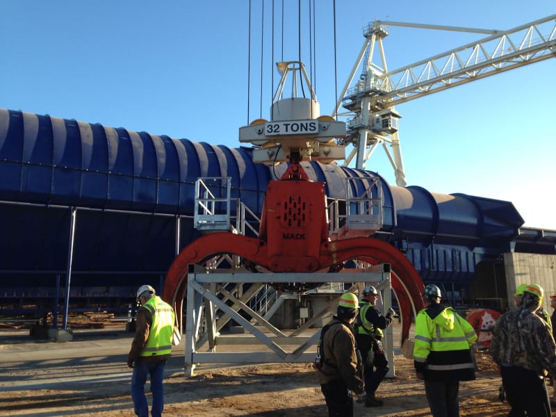
3D_grapple_photo_abfleu.jpg


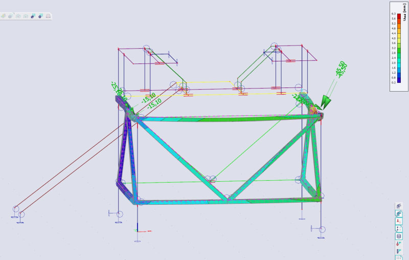
2) My current calculation model in SCIA Engineer.
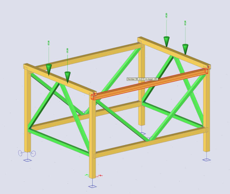
3D_grapple_calcmodel_qrdxkc.jpg


3) Close-up of a beam cross-section with two vertical point loads. One point load is equal to 150/4=37,5 kN. The beams are currently SHS150x150x8, so the eccentricity of the load is 75 mm.
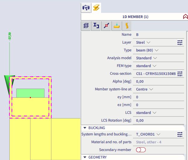
3D_grapple_calc-section_fmwdzs.jpg


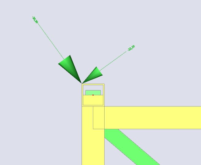
4) And a close-up with an angled load.
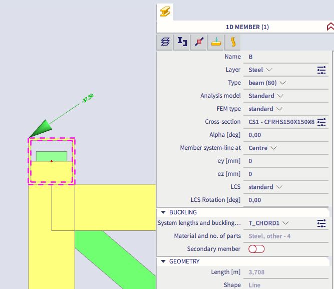
3D_grapple_calc-section_angled_rwka7n.jpg


So yeah, my main question is how does this grapple affect the side truss/beam. Is it going to push it outwards or inwards or something else.

Any help would be appreciated.
 
Replies continue below

Recommended for you

I think I got it myself. It's basically a load acting on the inclined plane. I have to just apply the components of the 37,5 kN. If the grapple leg is angled at 36°, then the outward pushing force is Fo=37,5*sin36°=22,04 kN and the inward pushing force is Fi=37,5*cos36°=30,3 kN. In the model it should look like this, I think:

3D_grapple_calc-section_angled2_nqfmtw.jpg
 
Why don't you make the frame less wide so that the frame sits on the horizontal parts of the grapple arms. This thing looks rather unstable and rely on friction (never a good idea) to keep the grapple hooks from moving?

Keep all or most of your forces vertical would seem to be a better plan to me....

Remember - More details = better answers
Also: If you get a response it's polite to respond to it.
 
It does not rely on friction - the grapple does not go wider. And since grapples of different width may be used, I don't think applying only vertical loads is the safest way to design this thing.
 
Keep in mind that you are only fabricating one. Do not be afraid to beef it up. I would include connection points to use a chain binder or similar to secure the grapple.
 
Well you could make that bar which picks up the hook moveable along the beam? Just provide a set of pins and slide the bars equally depending on the particular grapple?

My point is that it isn't easy to get the hook exactly in the middle so it might sit lopsided. You also end up with a huge point load on your box beam and it won't take many times to get some dents or even holes in the box beam. you're also going to get a fair moment connection on that cross beam at the corner posts which can be avoided by adjusting the cross beam to reduce or eliminate your sideways load.

Just thinking out loud here. If you can reduce forces, moment and stresses then it's generally a good idea. IMHO.

Remember - More details = better answers
Also: If you get a response it's polite to respond to it.
 
Could maybe just throw some 6x6 timbers on top as it is being lowered.
 
Nivoo_boss:
The shape of the stand kinda depends on what kind of maintenance you are going to do on the grapple. The center plan area of the stand has to remain open to avoid hitting the grapple linkages and to be able to work on them. It is assumed that in that open position, the grapple arms are hitting a max. open stop block above the linkage cage, so that a slight cable tension change will relax or tighten the linkage action, and allow linkage work. I agree with
LittleInch, 27OCT, 11:07, that you would probably be better off if your cross beams hit the grapple arms approx. at their underside horiz. arm surface. This would simplify that cross beam design and take most of the torsional loading out of those beams. I understand that you might have three or four different grapples and the cross beam spacing might change for each, but that’s just three or four sets of locator pin holes, for the cross beams on the main frame. I would fix a replaceable oak 4x6 to the top of each cross beam. Your picture #4 is wrong in the direction of the largest component (but not 37.5 kN either), your next sketch 27OCT, 10:37 looks correct. With your current frame, the horiz. components at the top of the cross tube will become much larger, and difficult to deal with on smaller grapples.

RE: your sketch #2, there is no particular reason to use all HSS tube sections for this frame, they are generally more expensive than other rolled shapes, stocky smaller WF shapes, etc., and not particularly easier to detail around. This whole frame could be fab. shop welded. On the long sides of the frame, I would invert the diag. bracing to help support the long top beam which carries the load, and make it a 2 span top chord, trussed arrangement. On the short ends, I would lower the top beam so that it would miss the tips of the grapple arms, but still brace the frame side to side. Leave the diag. bracing as it it oriented, this daig. bracing arrangement should make the frame a little easier to walk in and out of too. All four of the bot. horiz. members are now bracing members and should be closer to the ground, easier to step over.
 
This thing is in an industrial environment - you need to design it to withstand the unanticipated loading, not the weight of the unit. Forktruck strikes, misaligned lifting and lowering, shock loads, etc. Make it stout, including anchorage if it is fixed.
 
Even if it's only a foot, if the operator drops this onto the frame the will be significant shock loading.

Also think about access into the space.

The whole thing looks rather weedy to me.

I think it would need a proof test of at least 3 x static load.

Remember - More details = better answers
Also: If you get a response it's polite to respond to it.
 
The support frames we have built involve supporting the device so specific parts can be removed. I do not see what of any significance can be serviced with this frame. I suspect this grapple can sit on the ground. If so, I can service exactly the same parts if I merely put down some timber cribbing so the grapple is level. Now if you support it from the hook point, then you could take off the arms if they are damaged, replace hydraulics, bearings, fittings......
 
I don't really care, that's what the company ordered.
 
Ok, you may want to inquire what all they want to service. I would envision they would crib below the main body to service more parts of the grapple. I suspect the hydraulics of a grapple like this will have breakdowns from time to time. If they remove any of the hoses and they do not have a it secured very well your problem is very different than the simple statics you show now.
 
Returning to your original question:

1. I agree with your follow-up post regarding the applied loads being the components of the resultant load for the grapple placed exactly centered on the frame.

2. I suggest you consider the idea the actual placement of the grapple on the frame may be off. That is; the center of the grapple might not be directly over the center of the frame. It is not being placed with laser guidance (I suspect) so accounting for some eccentricity is warranted.

3. Consider the local effects of the applied load at a single contact point (about 3.75 T) and it’s effect on the tube wall. The wall is approx. 1/4”, so a 3.75T load may very well crush the tube.


4. The respondents’ posts make valid points. All should be considered and discussed with your client and/or manufacturer.

5. The photo shows a grapple placed on a stand. It appears the grapple is “fully open” - as in the individual claws are fully extended to their max. range of travel. If that is the case, then perhaps there are stops to prevent further spreading. This may address some of the concerns noted. Again - you probably can discuss with the client and/manufacturer and confirm those stops (if present) are sufficient to support the forces of the claw in the event of hydraulic failure.
 
Coming back to my old thread.

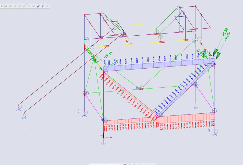
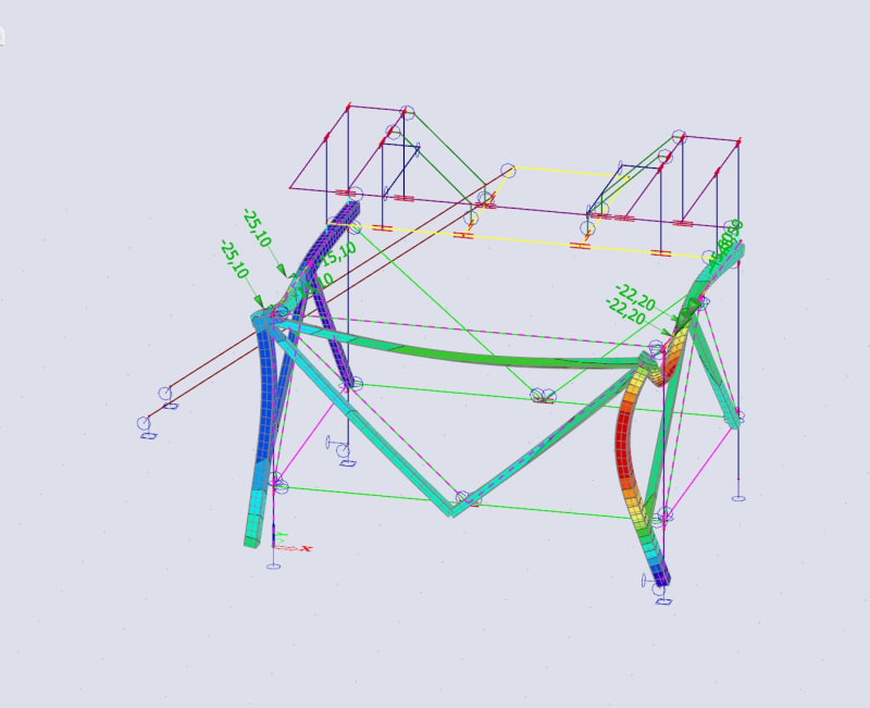
I still have doubts about the load components I presented in my second post. My gut feeling says that in reality this grapple would want to push the whole structure inward. But if I view the deformations from this kind of loading it does not deform inward, even the truss chord at the top (in the front) does not develop compression but tension instead. Below the first screenshot is with the deformation.

1) I know this kind of deformation happens because the net force of the components is vertical and eccentric in relation to the cross-section, thus sort of twisting the top chord. I can't just imagine it happening in reality.
deformation_roo67i.jpg


2) Internal forces, blue is tension, red compression. Neglible forces as you can see. Makes sense that since the top chord is in torsion it does not push the truss inward.
internal_forces_volspy.jpg


What do you guys think? Is this the correct way to apply forces to this beam? Don't you think in reality the grapple would push this thing inward?
 
Since the first screens were quite shitty, I'll put one more here with amplified deformations.

def2_zsfpch.jpg
 
nivoo boss said:
I still have doubts about the load components I presented in my second post.

I though your second post was on the right track, so I didn't say anything.

This problems is much easier if you forget about the frame for a minute and take a mechanical engineering look at what happens to the grapple:

3D_grapple_photo_abfleu-700_fg6cok.jpg


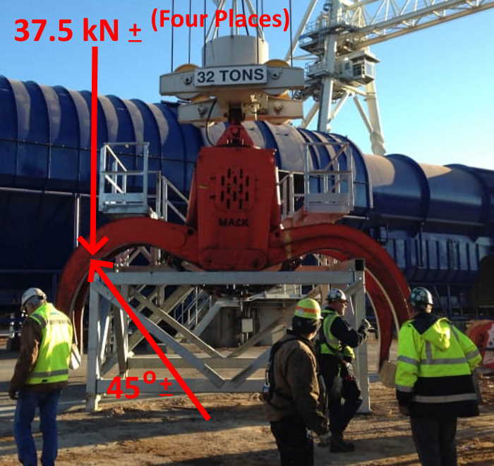
1) Force supporting the grapple has to be perpendicular to the "claw" at it's point of contact (neglecting fiction, a reasonable assumption).

2) You need the angle that the force (see #1, above) makes with the ground. Look at the photo you posted... the grapple manufacturer is "Mack".
Goggle will quickly take you to Mack's info on log grapples.

3) Using this info you should be able to make reasonable assumptions about the force contact angle (#2, above) for various size grapples that may be used.

4) Talk to your Client, and ideally, go look at and measure some of the grapples they plan to use. Improve your assumptions (#3, above) with this info.

5) With the weight (37.5 kN +) and the angle of the supporting force, you have what is needed.

6) Thanks to Sir Issac Newton, force, and it's direction on the frame is exactly equal to and opposite force on the grapple.

Another subject... You say you were hired to "...design a steel platform...". Why are you trying to exactly replicate what someone just "built"?

Use engineering principles to select/size members and to position members where it makes the most sense.

One change I would make for sure is to use round HSS, instead of square/rectangular HSS, as grapple support members. That way no matter what angle the perpendicular force on the claws makes with the ground, structural properties of the member (round HSS) are the same.
 
Status
Not open for further replies.

Part and Inventory Search

Sponsor