Eng-Tips is the largest engineering community on the Internet

Intelligent Work Forums for Engineering Professionals

Steel structure connection design for space frame cantilever

Status
Not open for further replies.

PSR_1

Civil/Environmental
Aug 9, 2016
56
0
0
ET
Hello guys.

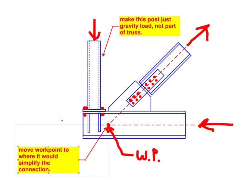
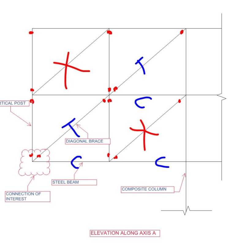
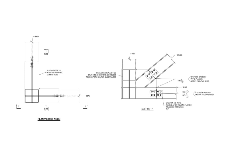
Recently I have come across a cantilever space frame structure( please see the attached pdf before reading the rest of the post for better clarity). for clarity of details I have attached pdf file showing some portion of the structure. while most of the connections are standard type, the vertical post, bracing and floor beam connection detail at the edge( clearly shown in the attached pdf) is a bit complicated. the two beams meet at 90 degree angle and due to the presence of bracing and vertical post, the beams develop moment at the end ( it doesn't become zero as a typical cantilever beam). the presence of this moment together with the axial load from both the post and the bracing makes the connection design a bit challenging. could you please provide some insight on how to idealize and design a fitting connection type? sample would be much appreciated.

please note that the structure acts as space frame and the floor system is composite concrete steel.
 
 https://files.engineering.com/getfile.aspx?folder=e4355600-135f-4359-b2d2-65a1267e9c86&file=SPACE_FRAME_CANTILEVER.pdf
PSR_1 said:
...the beams develop moment at the end ( it doesn't become zero as a typical cantilever beam)

I feel that the moment at the beam end should be zero. To do other wise is to lay claim to some version of Vierendeel Truss behavior. And that strikes me as foolhardy because:

a) Surely the cantilever response is dominated by the massive scale trussing and;

b) Vierendeel action creates precisely the kind of annoying and expensive connection detailing problems that you are currently experiencing.

Are you the engineer of record for this project? Or the delegated connection designer?
 
Hello kootk, I am delegated connection designer. Since most of the decision is already made, pushing for truss action would require them to go back and verify all the steps they did before.I don't think they would agree.
 
If you follow my recommendation below, the connection gets a whole lot simpler.

c01_pmcbzw.jpg
 
OP said:
Since most of the decision is already made, pushing for truss action would require them to go back and verify all the steps they did before.I don't think they would agree.

You don't need to push for truss action. Truss action will be the dominant behavior no matter what the EOR says. Loads follow stiffness and structures are notoriously bad listeners, particularly when they've been told stupid shit.
 
I'd consider issuing an RFI on this for the sake of:

1) The owner ($$$).

2) You (sanity).

3) Me (any engineer that might review this a part of future work).

4) The occupants (deserve a predictably/reliably designed and detailed structure).

5) The universe (preferring order and rationality in general).
 
I don't even understand the logic in the trussing. I think this would work just fine and have half the bracing members and half the bracing connections. Maybe you want the bottom right brace for erection...

c01_gzhie5.jpg
 
If you are forced to follow the original approach, I suspect that the way to go would would be to fabricate the entire joint in the shop as a 3-D super node. Then connect all of the incoming members with field moment splices. For that scheme, you'd be much better off with the post as wide flange rather than HSS so that you could get some flange plates on it.

If the post can't be switched to a wide flange, maybe you run the post through the joint continuously with some pass through horizontal stiffeners to reach out to the incoming beam flanges. You'd need three levels of these diaphragm stiffeners as one would probably need to hit the upper flange of the brace as well.
 
Maybe I'm just an idiot, or blind, buy WHY do you need to have both of the beams coming in to that corner moment connected? You have a vertical brace coming into that corner from each side. Is there no floor diaphragm at this level? If not, moment connections are a real nasty way to try and gain stability.

An aside, from the plan view, it APPEARS, based on the moment connection triangles surrounding the column at C.L. 2 (assumed) and C.L. A that the column is suppposed to break the beam (otherwise, just draw the beam underneath as continuous - Surely you can get an 11540mm [~39') long beam). If the intent is to have the columns on the top of the beams, based on the same 2A column, you'd STILL need to transmit the moment from the N/S (plan up/down) beam into the column as surely the wide flange isn't supposed to react that end moment via torsion.

Same story at your corner column (1A) - the beams are shown to transmit end moments, but if they are framing into each other, you're dumping torsion into each beam. If the intent is to move that end moment up into the column, then good luck.

At any rate, I would push back to the EOR and ask for a detail that communicates their intent at each of these connections.

Please note that is a "v" (as in Violin) not a "y".
 
Status
Not open for further replies.
Back
Top