Continue to Site

Eng-Tips is the largest engineering community on the Internet

Intelligent Work Forums for Engineering Professionals

  • Congratulations waross on being selected by the Eng-Tips community for having the most helpful posts in the forums last week. Way to Go!

steel support anchored to existing RC parapet 1

Status
Not open for further replies.

gmd255

Structural
Apr 17, 2017
49
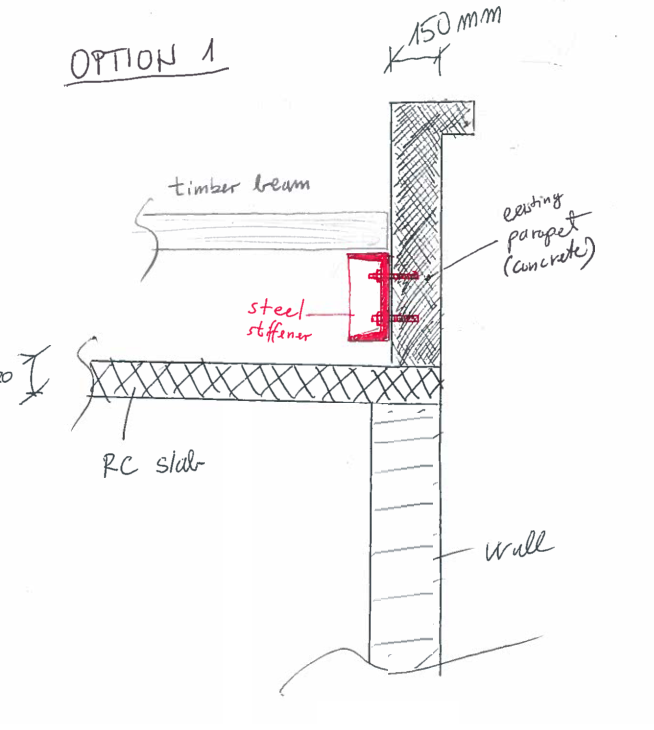
I have an existing RC parapet that is 150 mm thick.
I would like to anchor a steel support to this parapet.
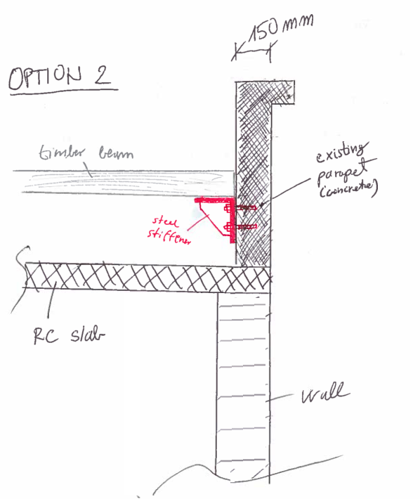
Steel support (beam) is a bearing seat for a timber beams along a parapet.
I have two options. Id like to hear from you what do you think/suggest.

OPTION 1
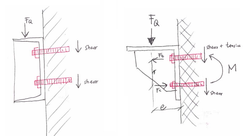
I have steel C section + stiffener (at a spot of concentrated load from timber beam). As far as I can see, there will be only shear forces in bolts. Correct?
What is bothering me is a fact, that a flanges are very short with this kind of steel profile. So a steel C section with height of 200 mm has only 75 mm long flanges. I dont need such big profile (height of section so its not really economical to choose big dimension just because of that). How much bearing seat is enough in your opinion?

OPTION 2
Bearing seat is not a problem, but what I dont like is the fact, I get tension forces in bolts. That is a problem since existing parapet is only 150 mm thick. Also reinforcement in parapet is at minimum.

What do you guys suggest? Have I overlooked something?
oo1_z4jux8.png


oo2_wuxwfi.png


oo_qg13rm.png
 
Replies continue below

Recommended for you

Well the crucial Question is...how much load is there
I understand it is a seat for Grandma :)
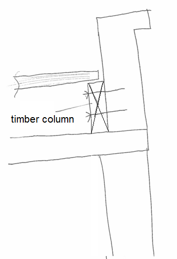
I dont see a problem... but you can just put a short column under the seat and the no force to the Wall


best regards
Klaus
 
Reaction/force FQ per timber beam is around 30 kN.
Timber beams are 1,10 m apart.

 
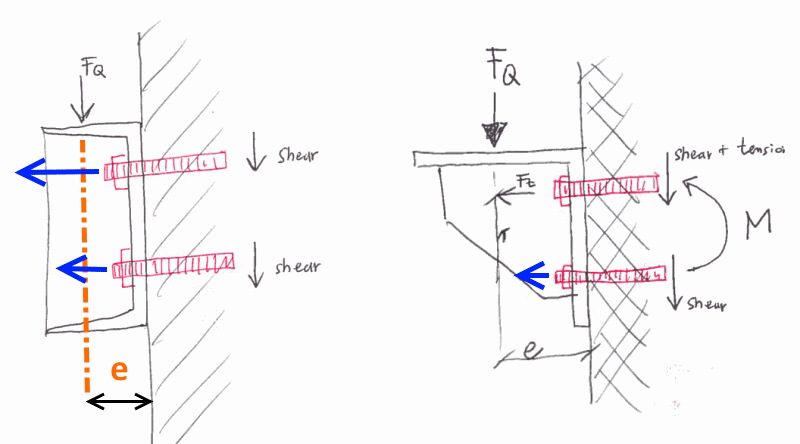
The load, F[sub]Q[/sub], is eccentric with both the channel and and the angle. The section tries to rotate about it's lower right hand corner. This puts both shear and tension in the two anchors for the channel and the two anchors for the angle. How the shear and tension are shared between the the two anchors can be complicated and depends on the hole size shape and location in the steel member. I've marked up your sketch, see it below.

In most cases 75 mm is adequate for a beam seat.

I would use an unequal leg angle sized (thickness) so that the stiffener is not required.
The longer leg of the angle is next to the concrete.
The unequal legs allow the bolts additional spacing for the concrete anchorage, and more lever arm for the bolts to resist the moment.
Not using stiffeners reduces the chance of mislocating it during fabrication or installation.
Load, F[sub]Q[/sub], from a timber beam cannot be very high when compared to the allowable load for the outstanding leg of a suitable angle.

Bracket_tagmr5.png


[idea]
[r2d2]
 
SlideRuleEra thank you for elaboration. It make sense!

I am still kinda worried about parapet being only 150 mm thick. I have to check what are manufacturer's requirements for anchors.
 
You are welcome. If possible, bolts that go through the wall are probably better than anchors.

Keep in mind that drilled holes for for either anchors or through-bolts may not go where you want them. For example, existing rebar may be in the way. In your design, allow for anchor relocation as much as possible.

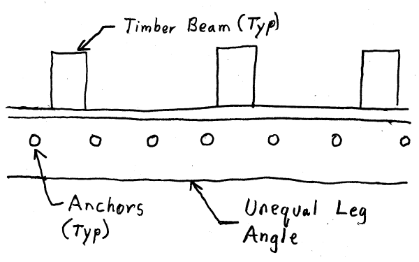
A design that I have used is to have a single line of anchors spaced along the length of the angle. Then, the shear and tension on each anchors is more predictable. A heavy angle allows the anchors to be further away from beam centerline, yet still contribute to beam support. Also, relocating the hole in the angle (when required) is not a big deal. Still have to be follow manufacturer's anchor spacing requirements.
Here is a sketch of this concept, looking parallel to beam length:

Angle-1_v65c0m.png


[idea]
[r2d2]
 
Great, I agree completly! Good advices - big thanks again.
 
One more thing!

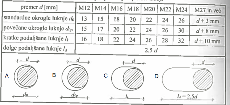
Would you guys consider elongated holes (horizontally) in steel angle, since the beam will be outside (exposed to change in temperature from -20[sup]o[/sup]C to +40[sup]o[/sup]C)

Steel angle (beam) is 7,50 m long.

I calculated that the expansion of the beam is 5,50 mm (for ΔT = 60[sup]o[/sup]C).
 
IMHO, elongated holes... no.
Oversized holes... those should be used anyway, without regard to thermal expansion.

Retrofit work, like this, is different than new work. If the design is made strictly using new work practices, there will be many field problems that don't have a good solution.

For example, there is no guaranteed that field installed anchors (or holes for through-bolts) will be perpendicular to the concrete surface. In fact, many of them will be at slight odd angles... in multiple directions. Expect interference (in the vertical direction) with the horizontally slotted holes.

Another example, if an anchor has to be relocated (say because of conflict with existing rebar), it will probably be necessary to make a new hole in the angle. Then drill the the hole in the concrete through the hole in steel.

Along those sames lines, don't install the minimum number of anchors to carry the load.
In accordance with the anchor manufacturer's recommendations... install as many anchors as practical. Some anchors may not be usable. Also, since (by necessity) the design does not follow accepted practice for new work, the anchors should be as lightly loaded as possible.

Concerning thermal expansion, I agree with your 5.5 mm change. However, the concrete temperature is likely to be similar to the temperature of the steel. Thermal expansion coefficients as similar for concrete and steel. The concrete is not going to be -20[sup]o[/sup]C at the same time the steel is +40[sup]o[/sup]C. Maybe, say, 20[sup]o[/sup]C difference, but never 60[sup]o[/sup]C.

Also, it is unlikely the steel will be installed when the temperature is either -20[sup]o[/sup] or +40[sup]o[/sup]. Thermal expansion and contraction will probable be based on a more modest temperature. Say, installation at +20[sup]o[/sup]C, with possible temperature changes being +20[sup]o[/sup] or -40[sup]o[/sup].

[idea]
[r2d2]
 
Another avenue that could be explored is using facemount hangers at each individual beam. Either mass produced cold formed hardware or a pair of clip angles with a bearing plate welded to the bottom. Potential advantages:

1) You may need a way to prevent beam rollover anyhow depending on your proportions.

2) No thermal issues.

One of the few nice things about a 6" concrete wall is that there is a high probability that the reinforcing is a single mat centered within the wall thickness. You could potentially spec 2.5" embedment anchors and stand a pretty good chance of not having any rebar interference.

I like to debate structural engineering theory -- a lot. If I challenge you on something, know that I'm doing so because I respect your opinion enough to either change it or adopt it.
 
Can you not just put timber 'stub' columns beneath the beam? with a lag going into the wall for lateral tie?

Dik
 
SlideRuleEra you really put some thought to that. Looks like you are really experienced in that field. You also explain it so well. Thank you. Will return a favor if possible. When I was talking elongated holes - i wasnt thinking option D, I was more like option C. If I undesrand you correctly (English is not my 1st language) you were refering to option B - isnt a vertical slip problematic in this case?

holes_w2gtsh.png


Kootk - I dont really like the idea of facemount hangers at each individual beam. Since I have around 15 of timber beams along a parapet, it is much easier to install one beam as line support for all beams than multiple hangers (in the same line - height).

dik - in that case Im dealing with the same problem as mentioned above. Id like a line support. A wall below a parapet/slab is 200 mm thick (parapet is 150 mm) so there is 50 mm difference. Maybe I can put timber beams on a wall/slab, but I dont really like that idea. I also dont want to load a slab in any way since I have no data about it but it looks in pretty bad shape.

111_rqbhvk.png


1121_asozly.png


However, I was thinking about why not replacing steel angle with timber beam along the parapet. This beam will be well protected from outside/weather (there will be plywood + hydro insulation above timber beams). But in that case Id need to place washers.
 
Because the wall beneath the slab extends a bit beyond the parapet, the load will produce little if an shear and normally slabs with a continuous support do not have shear problems. Just seemed to be the easiest and cheapest manner of support.

(Added) Installing anchorages into an existing parapet could be problematic, too.

Dik
 
I'm with dick on the post down to the slab. Negligible slab impact there.

How are you going restrain your timber beams with regard to uplift and end rotation? It seems to me that you're going to require some hardware at each beam for those purposes no matter what. And that's why I thought that the individual hangers might appeal. If you need some hardware at each beam regardless, might as well have that hardware to the gravity support job as well.

A timber ledger with face mount hangers might work well too of course. From a durability perspective, it might be nice to use a pressure treated ledger so that you don't have any wood in direct contact with the concrete.

I like to debate structural engineering theory -- a lot. If I challenge you on something, know that I'm doing so because I respect your opinion enough to either change it or adopt it.
 
KootK: I'd use PWF material for all wood in contact with concrete... just a standard practice.

Dik
 
gmd255 - Thank you, I have done a lot of this type work - most of in in heavy industry.
All of my suggestions are based on the magnitude of the load:
Reaction_at_Bracket-1_yzbbhh.png

30 kN (6740 lb.) load from each end of each timber beam requires attention to details. If this load estimate has been significantly reduced, other solutions should be considered.

Suggest determining if the 6" wall can take this load (spaced every 1.1 meters).
Determine what size bracket and what size/type anchors (or through-bolts) are practical.
Then the details of bracket / anchor design can be addressed.

Concerning your question on bracket hole size. Oversize hole "B" in your diagram is what I have in mind. An angle bracket 7.5 meters long is probably going to have 40, or so, anchors in it. The chances of installing 40+ anchors in the wall (even using a full size, accurate wooden template) then being able to slip the bracket onto those 40+ anchors are essentially zero.

The only way to make this work, in my experience, is to mount the bracket on the wall with at least 2 anchors, then drill the remaining holes through holes in the bracket. I don't have current info on anchors... but say that 3/4" diameter chemical anchors are used. A hole perhaps 7/8" diameter needs to be drilled in the concrete. To do this the hole in the bracket should be, maybe, 1" in diameter.

Yes, the holes are oversized, and (theoretically) there could be some movement. However, in practice, each of the 40+ anchors will be installed somewhat off center or angled so that the bracket is wedged in place and could not be removed if you wanted to do so. Install appropriate washers and nuts, and try to make the bolting approach slip critical. It will not be slip critical... I know that. But if the work is done with care and attention to detail it will work... and will be successful.

For what it's worth, using this method for very heavy loads, an elevated walkway rehabilitation project (design, contract prep/award, construction management, etc.) I completed 26 years ago is still used daily by hundreds of my former co-workers. No alterations or other changes during the 26 years.

By the way, I consider your use of English to be excellent.

[idea]
[r2d2]
 
Amazing... I'll keep this advices/suggestions in my mind. Its great that some of you share your knowledge with young/inexperienced engineers. this site is great. Tnx again.

About steel bracket - I calculated that 100 mm of bearing seat for a timber beam is just enough, so I was thinking about steel angle about 100 x 200 mm (with longer leg anchored in parapet). Vertical spacing between bolts will be around 150 mm so forces wont be that large.

About anchors - I was thinking about chemical anchors or mechanical (expansion anchor) as shown in link below (I used them before, they are one of the best for pull out forces and they dont need much of embedment depth - around 80 mm).


Chemical anchors (in my experience) usually demand more embedment depth and since I have a 150 mm thick parapet I think I will stick with mechanical/expansion anchors. BTW I dont have an access on the outer side of the parapet (there is a wall of nearby building next to it) in case anchors go through the parapet.

As soon as I determine bracket and bolts (number and spacing ) I will calculate forces on a parapet and check its bearing capacity.

Kootk - as far as uplifting forces goes - There are few options about connecting timber beam to steel angle/support. I was thinking about small/short steel angles. Im not concerned about rotation of timber beams - there will be a sheating with timber boards or plywood on top of beams in combination with steel angles mentioned above. I cant really use hangers along the whole lenght of parapet (at least not manufactured ones) since parapet wall in at 20[sup]o[/sup] (looking from the top) at some parts.

aaaa_bvtqmp.jpg
 
Status
Not open for further replies.

Part and Inventory Search

Sponsor