dcarr82775
Structural
- Jun 1, 2009
- 1,045
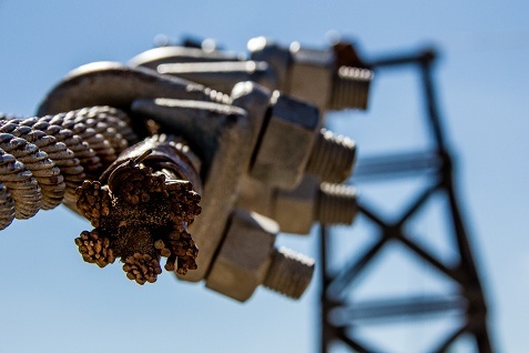
Somebody posted a picture of this suspension bridge over in the Earth retention Forum. I was looking at the anchorage in horror. Went looking on the internet, and found the following
Sadly, not too surprising
Sadly, not too surprising