Eng-Tips is the largest engineering community on the Internet

Intelligent Work Forums for Engineering Professionals

  • Congratulations waross on being selected by the Eng-Tips community for having the most helpful posts in the forums last week. Way to Go!

Steel truss and concrete column connection

Status
Not open for further replies.

Jummybear

Civil/Environmental
Jul 24, 2014
10
EE
Hi all,
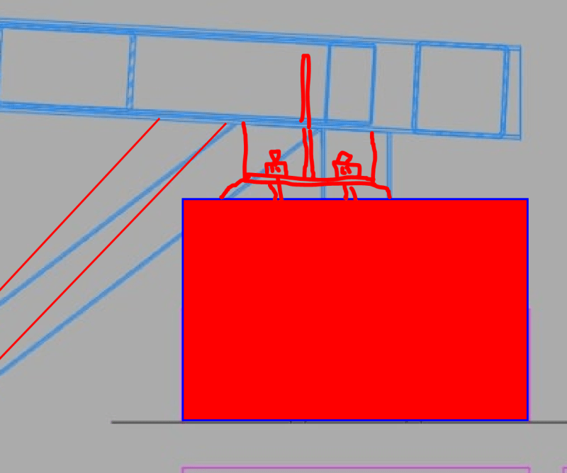
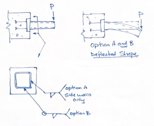
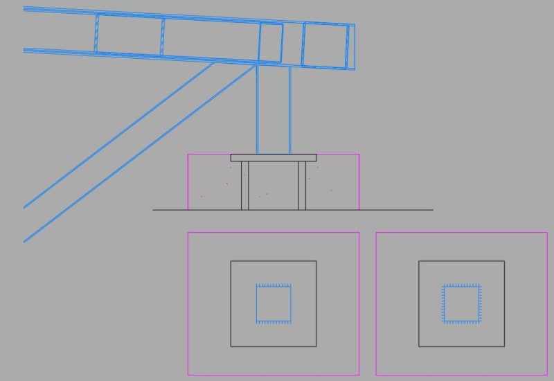
I want to discuss such type of connection where steel truss is welded to anchor plate installed on the top of concrete column. Steel truss is welded with fillet weld. It is considered that joint is rigid when truss post is welded around. My question is it possible to consider such joint as pinned or semi-rigid when welds are provided only on 2 sides?
Capture1_zpat0r.jpg
 
Replies continue below

Recommended for you


If the bottom cord does not extend to the column face and if not connected , the truss essentially pin connected to the column. The stiffness of vertical truss element ( bbtw RC column and truss top chord ) is negligible when compared with truss stiffness.

If you need moment connection , it should be similar to the following sketch .

truss_moment_connection_i5ywaq.jpg


IMO, the moment conn. btw RC column and steel truss is not good a idea ..


Not to know is bad;
not to wish to know is worse.

NIGERIAN PROVERB
 
@Jummybear: I don't love the overall connection setup. Are you in a position to modify it if you wish? Does the connection need to transfer wind/seismic/stability loads into the truss?

Jummybear said:
My question is it possible to consider such joint as pinned or semi-rigid when welds are provided only on 2 sides?

If you go with the original connection, I definitely would not go with the two-sided welds. That will not meaningfully encourage pin-ish behavior and will, instead, increase the likelihood that flexural stresses will rupture your two sided welds where they terminate in an unpleasant, fracture mechanics kind of way.
 
HTURKAK
Truss bottom chord doesnt connected to the column so in my global frame model I use pin connection between truss and rc column. I dont need moment connection to my frame in upper joint (truss-rc column).


KootK I agree with you that its not the best one, but very common solution here. Another one is with anchor bolts instead of anchor plate and welding. We can try to suggest another solution but with no guarantee it will be accepted.

The connection need to transfer wind load as well, yes, in both direction. The roof is used as bracing element, so columns get their support at that level as well. In the direction perpendicular to the truss this joint should be able to carry moment from bracing force (in the roof plane).

I am also very cautious with this two sided welding but had a conversation today with another engineer who said he was used such solution and he has almost convinced me about it. His arguments were that you remove those 2 sides of welding, which should work in moment direction most efficiently and you get closer solution to pinned joint if it was welded all around. When I asked about remaining side welds behavior he said that it will obviously yield at the ends but this "yield zone or length" remain quite small and local in comparison with total length of the weld seam.

I feel myself a little bit confused about such solution and our conversation so I decided to bring this topic here.
 
OP said:
His arguments were that you remove those 2 sides of welding, which should work in moment direction most efficiently and you get closer solution to pinned joint if it was welded all around.

I'm afraid that your colleague doesn't know what he's talking about. Feel free to send him to this thread to defend his ideas.

OP said:
When I asked about remaining side welds behavior he said that it will obviously yield at the ends but this "yield zone or length" remain quite small and local in comparison with total length of the weld seam.

Fillet welds don't typically yield in any desirable, controlled fashion. Rather, then tend to fracture and unzip. We generally look unfavorably upon things that fracture and unzip.

If this is to be a he said / she said thing, hopefully some of my ET colleagues will show up here to back me up on this.
 
I don't know what the acronym ET is so I assume I don't meet the criteria, but I will back you up Koot
I have always been taught that welds are technically 'ductile' but they're ductile over such a tiny length that the overall behaviour is effectively brittle and they unzip and the stuff falls over
I would never rely on any form of 'ductility' or 'yield zone' in a weld in the way that you say your colleague has described it

I went to a course from some welding/fatigue/fracture expert a few years back and weld details like the ones shown there were explicitly called out as bad practice
He said you end up with an undefinable stress concentration at the tip that leads to early failures as Koot described
Proper welding practice would always be to return the weld around the corner, if not to weld the whole way around
 
Thanks GreenAlleyCat. That's a fine point regarding the return weld around the corner practice.

ET = Eng-Tips. Goes to show: there's just no such thing as a safe, undefined acronym.
 
Even if the welds are not located on the correct sides for a moment connection (i.e. top/bot flange components), the welded sides will still be quite stiff which means you don't really attract that much less moment to the connection. As KootK mentioned all this will do is stress the extreme weld beyond capacity, which will then cause it to fracture thus increasing stress on remaining weld...and so on until it unzips.

If you think about a standard shear tab connection we specifically design the welds along the tab so that pretty much everything other than the welds will yield first. If something goes wrong in the connection we want it in the ductile components (e.g. the steel tab itself).

Is there anyway we can use CIP anchors instead of a CIP baseplate? The anchors can be sized/positioned to allow for enough rotation that it will be nominally pinned. And then we don't have any qualms with welding all the way around.
 
Woops. I just assume all unknown acronyms on this forum are some form of Americanese!

I have now learned my new thing for the day, time to go back to bed to process my newfound knowledge
 
I'd prefer something that looks more like this, especially since wind load and stability demands on the column factor in. This is similar to how joist suppliers deal with these situations in the bearing seats of their trusses and you can trust that their solutions have been well vetted such that they represent sound practice. Even if you prefer to weld to an embed plate rather than anchor, I still like the proportions of something like this much better.

c01_kzfs2z.png
 
Koot, not disagreeing with your solution, I just can't tell if you're being sarcastic that a proprietary product supplier can be considered to provide 'well vetted good practice' details
I tend to look upon anything proprietary with the same level of trust as a black box full of WW2 era explosives - Schrodingers reliability
 
GreenAlleyCt said:
I just can't tell if you're being sarcastic that a proprietary product supplier can be considered to provide 'well vetted good practice' details

I was being completely sincere. I consider the details of a reputable supplier -- and their trade association -- to have been vetted via a process akin to evolution. Obviously, every detail has an appropriate range of application that needs to be respected.

In this situation, that tall bearing leg thing strikes me as altogether unwise for what is, essentially, a top chord bearing truss. It invites incidental moments, direct moments, and inherent stability problems. Raising the support closer to the bearing node of the truss alleviates all of that stuff and I assume that is, in part, why joist suppliers do that.
 
I've lost faith in proprietary suppliers after finding issues in details or calculation programs from two major suppliers
Funnily enough the email chain always cuts out as soon as you point out the flaw...

 
You'll note that I never actually used the phrase "proprietary" originally. In North America, many aspects of joist detailing are prescribed by the joist supplier trade organization known as The Steel Joist Institute. They are to steel joists as the American Concrete Institute is to concrete. My faith resides more with that organization that it does with individual joist manufactures who, like me, are probably very fond of money.
 
I think HTURKAK nailed it in the first reply to this thread. The OP’s original detail should be considered pinned, but it should be welded all around. We typically consider this type of column connection pinned.
 
I'd have to look back in the archives for some details, but I will say that while all of the statements above about weld ductility are generally true and the standard practice, I did apply a very similar principle on a design several years ago. E.g. designed a fillet weld connection specifically to allow a moderate amount of rotation (enough to consider it a pin connection analytically) under some very heavy, very real loading (not ethereal lateral or earth pressure loading).

My approach was to provide very short (and located near the center of rotation), very large fillet welds that met the criteria for rotational ductility in the AISC manual (p 9-17)

Whether by luck, design factors, or being correct, it did work.
 
Jummybear said:
My question is it possible to consider such joint as pinned or semi-rigid when welds are provided only on 2 sides?

Discussing the connection of the HSS to the embedded plate in isolation, I consider the 2-sided weld to be rigid. It restricts end rotation just the same as if the HSS were welded all around. Consider a test case as shown in the sketch below. An HSS welded to an embedded plate in (2) ways. Option A is welded on the side walls only and Option B is welded all around. Under load, the deflected shape of each HSS would be essentially the same. The difference being the option with welds on two sides only would fail at a much lower load and likely more suddenly due to maximum stress being located at the termination of the welds.

Capture_flyces.jpg


I've seen this misconception on eng-tips and in practice often - just because you have removed rotational strength from a joint does not mean you have removed rotational stiffness. Stiffness attracts load and you better have strength to match. This is a perfect example. If welded two sides only, the welds restrict end rotation of the HSS and attract the associated bending moment that goes with that stiffness. The side welds are positioned poorly to transmit the rotational forces they have attracted.

The suggestion to assume a pinned condition may be appropriate and conservative for the design of some elements of this structure like the truss itself, but it would be unconservative to assume a pinned connection for the design of this welded joint and stub.

I agree with KootK's suggestion to extend the concrete column up and bolt the truss direct to the column. If you have to keep the HSS stub for some other reason I would try to bolt it down with a base plate and anchor rods. Field welds are expensive, especially when you have heavy equipment holding something in place while you weld it.
 
I don't like the half weld nor the space between the truss and column either. I have seen a lot of issues in the field with various truss types and bearing details that I don't like to mess around here. Trusses by nature just attract more failure types and a bad bearing detail is just asking for the top of the column to be broken in the future.
 
Rather than a fillet weld at the bottom, can you use a couple of clip angles so there is some rotational capacity provided by the legs of the angle?

-----*****-----
So strange to see the singularity approaching while the entire planet is rapidly turning into a hellscape. -John Coates

-Dik
 
KootK said:
Even if you prefer to weld to an embed plate rather than anchor, I still like the proportions of something like this much better.
The proportions and geometry of the joint will be changed, it was just a sketch from preliminary design. The main point I wanted to discuss was welding on 2 sides and how this may affect the joint itself.

CANPRO said:
The suggestion to assume a pinned condition may be appropriate and conservative for the design of some elements of this structure like the truss itself, but it would be unconservative to assume a pinned connection for the design of this welded joint and stub.
That`s a good point, I was thinking in a similar way. It may be pinned for truss calculation model and for global model, but for joint itself it a bit unconservative if welding is used.

dik said:
Rather than a fillet weld at the bottom, can you use a couple of clip angles so there is some rotational capacity provided by the legs of the angle?
Can you make a sketch? I didnt get your idea.

PS When using anchor bolts instead of welds what do you suggest for bearing between steel and concrete: steel, neoprene pad or concrete grouting?
 
Status
Not open for further replies.

Part and Inventory Search

Sponsor

Back
Top