Eng-Tips is the largest engineering community on the Internet

Intelligent Work Forums for Engineering Professionals

Steel Truss Bridge, Stringer Repair Detail

Status
Not open for further replies.
Oct 31, 2023
9
0
0
US
Hi everyone,

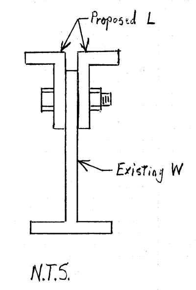
I would like to get some opinion / inputs on a detail that I have put together for stringer repair on a Truss - Floor beam - Stringer system bridge.

A little background info on the bridge - Very Old Steel Truss bridge, Ard 1910's. Currently closed to traffic and, the repair design is just to serve as a ped bridge. Bridge is in very bad shape (truss elements and gussets deteriorated). The deck on the truss spans (3 spans) will be replaced to meet current standards.

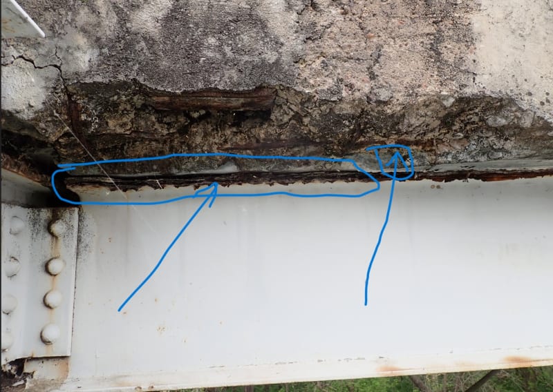
Stringer Deterioration and Repair Info - The top flange of stringers (both fascia stringers) exhibit severe corrosion, lamellar rust and section loss with separation from deck interface clearly visible on some. Since the bridge is very old, kind of trying to avoid welded details as multiple sources say to avoid welded details on very old steel structures, and also from a point of view of trying to make it a better fatigue detail.

So was hoping for inputs / criticism / suggestions on the drawing.


Thank you everyone. Eager to hear responses.


Replies continue below

Recommended for you

There wasn't any sketch attached. Anyway, on the left side of the photo, is the flanged gone? My suggestion, since you're replacing the deck, replace the deteriorated stringer(s.) Flanges are a messy repair when there isn't any meat left. Post your sketch and I'll take a look.


Deterioration_Photo_1_mopihp.jpg
 
Hi BridgeBuster,

Yes, that's correct. The location you marked is the area of complete separation of the top flange (lamellar rust) with the deck interface. And, given how the bridge is just going to be a pedestrian bridge, the clients preference is to repair rather than replace. here, is the missing link to the repair detail.

I appreciate your help and time in replying to my questions. Thanks.

 
 https://files.engineering.com/getfile.aspx?folder=f377a3ea-a48f-4143-901c-5202d81c2ef5&file=Repair_Detail.PNG
Have you checked to see if the beam is still adequate for the loads, even with the section loss? If this was a highway bridge before that's being repurposed as a ped bridge, you may not need to restore the original capacity to make it adequate for the new loads.
 
@BridgeSmith,

No, I have not performed the analysis to see if the stringer has adequate capacity even after the section loss. I would assume YES given how we were driving a 35' Snooper for the inspection, and we did not die LOL. However, the City (Client) wants to fix all possible defects now that they have ample funds and we are replacing the deck.
 
@Enjoy learning_not working - you're detail is fine, perhaps make the stem an inch or two long. Burning off steel isn't always clean. This way you have enough edge distance in case the cutting doesn't go well.
 
ELNW said:
No, I have not performed the analysis to see if the stringer has adequate capacity even after the section loss.
I would assume YES given how we were driving a 35' Snooper for the inspection, and we did not die LOL.

Revisit that assumption with calculations. Perform the calcs BridgeSmith recommended. If you use a widely accepted pedestrian bridge live load of 90 PSF, there is a good chance the structure will fail... and do so by a wide margin.
Don't LOL that the odds of that load happening are "impossible". Cities sometime offer large scale public events... like the Cooper Bridge Run & Walk in Charleston, SC (a small city). Every spring 40,000, or so, people run / walk across the modern cable-stayed bridge over the harbor:

Cooper_River_Bridge_Run-500_l0kox9.jpg


The bridge design was based, in part, on that pedestrian loading.

Concerning your proposed repair detail... a nice start. However the repair is not symmetric about the Y-axis... not good. Use a pair of angles bolted to the web to maintain Y-axis symmetry. When plate girders were fabricated with rivets, that was the "standard" way to address this issue. Also, do the calcs to determine bolt spacing... I expect you have far to many in the detail. Modifying and installing those bolts is expensive, labor-intensive work.

Edit: BridgeBuster - did not see your post when I posted. Would have worded my response more diplomatically... sorry.

Beam_Repair-400_yp00hn.png
 
Revisit that assumption with calculations. Perform the calcs BridgeSmith recommended. If you use a widely accepted pedestrian bridge live load of 90 PSF, there is a good chance the structure will fail... and do so by a wide margin. Don't LOL that the odds of that load happening are "impossible".

I agree that the 90 psf ped LL is very possible. For a vehicle bridge with a sidewalk the AASHTO ped LL is 75 psf (with a 1.75 load factor).

Given the location of the section loss on the top flange at the end of a stringer, where the moments will be small, I would not expect the uniform ped LL to be critical. However, I could certainly be wrong about that, so nothing should be assumed about the capacity of that stringer, or any other components. The ped load could and probably will be more critical than the original design loads, especially on the floorbeams and main trusses.
 
Yeah, my bad guys, definitely should not have LOLed at something which could have devastating effects in the future. I have indeed performed calcs but just not from a moment capacity point of view, only looking at shear for transfer of load through bolts. I'll lay out my thought process and the steps in designing this detail, all inputs are appreciated.

1. Restore the section to its original section - that would likely be sufficient for moment capacity given how the losses are at the top flange and at the ends.

2. Performed load calculations to compute the reaction at each end of the stringer (Taken the 90 psf Ped load as mentioned in the AASTHO Design for Ped Bridges 2009 Spec). The original rivets were 3/4" but the new reactions mandated use of 0ne (1) row of 7/8" HS bolts.

3. Spacing for the bolts - as per AISC manual, the min spacing is 2 2/3 x d, recommended is 3 x d = used this to provide a spacing of 2.5".

4. Edge distance for 7/8" HS bolts = 1 1/8", used 1.5" to be safe.

5. Splice plate was designed as a slip critical connection. That offset on the top flange is really bothering me but I dont have an idea if that is a make-or-break deal (just went along with the direction of my supervisor who said it really does not matter)

6. As an EIT I initially had recommended use of double angles on either side as SlideRule has drawn but my supervisor (whose stamp will be on the plans) directed to use T section. So, that was the reason for this detail.

So, with these points, does anyone feel it should be different or see any glaring deficiency in this detail?

Thanks once again for everyone who has provided their inputs.

 
ELNW - IMHO, Creating a slip critical connection in the field, on deteriorated 110+ year old steel is overly optimistic. I suggest trying to avoid relying on slip critical.

Looks like the existing WF is most likely a 1907 Bethlehem B15 (I = 465 in[sup]4[/sup], S = 62.0 in[sup]3[/sup]... when new). The new T section appears to me to be way oversized (probably not "bad", but a waste of money). Is there a standard WT section (shop fabricated from a W section) that could be used instead?

I totally disagree with your supervisor's overruling your double angle proposal... but that is out of your control.

 
SRE,

The beam closely resembles the B15 but is actually a B65 from Carnegie Steel Company with I = 406 and S = 54.1 (man getting that info and ultimately my hand on the original pocket companion was totally fascinating). There definitely are standard WT sections that closely matches the Section modulus, but the chosen section is such that it closely matches the web and flange thicknesses and the width that would closely align in plan with the original section. Hence, the T section with given dimensions. Also did not call out the W section specifically as I wanted the contractor to give us other options if they opted to.

Will definitely look into the suggestion of avoiding using slip critical connection criteria for the splice. Thanks, SRE.
 
ELNW said:
Also did not call out the W section specifically as I wanted the contractor to give us other options if they opted to.

One more comment. Just for fun, I played the part of the Contractor... since once-upon-a-time I was a bridge contractor (and already a PE at that time).

Looked thru W sections, S sections, M sections, and HP sections. There are no stock sections I could find that even comes close to simultaneously meeting the specified requirements:
Flange Width: 7 1/2" +
Flange Thickness: 5/8" +
Web Thickness: 3/8" +

However, I would meet the requirements exactly by doing the following:
Have W10 x 54 shop fabricated (10" wide flange cut to 7 1/2" width) and web cut to total 4 1/2" length... and charging the Owner a pretty penny for doing so. At least I would be able to get two of these custom shapes from one W10 x 54.

Surely you can do better than that. Suggest you design what is needed, don't delegate that to a Contractor. You are in the best position to know what is really needed. If you want options, specify the most important criteria (say, flange width) and tell contractors to make "suggestions" (which will likely be cost effective) for your consideration and acceptance.

 
Status
Not open for further replies.
Back
Top