Continue to Site

Eng-Tips is the largest engineering community on the Internet

Intelligent Work Forums for Engineering Professionals

  • Congratulations MintJulep on being selected by the Eng-Tips community for having the most helpful posts in the forums last week. Way to Go!

Stent simulation with Abaqus: questions and doubts 1

Status
Not open for further replies.

lucaam86

Bioengineer
Feb 26, 2017
10
Hello everyone,
I am a researcher in the field of biomedical 3D printing and I need your help on a Abaqus software. I am a new user of this software, and I would like to ask questions to you who are more experienced than me.
I should achieve an opening simulation of a stent (medical device) within a vascular branch. I know all the physical-mechanical characteristics of the stent and the vessel in which the stent will be in contact.
I also followed several tutorials but I have some doubts. In particular I would ask the following information:

- Boundary Conditions: I have not figured out how I should set the boundary conditions of my system to enable analysis. I have to prevent the roto-translation for each elements (vase, baloon and stent) in all directions of the space?

- If I wanted to compress the stent of a specific amount, how could I do? For example: the initial geometry of the stent has a diameter of 30mm, with Abaqus I would like to apply constant pressure on the outer surface of the stent so as to compress it from 10mm up to do to reach its diameter to 20mm. How can I make something like that?

Thank you.
Luca
 
Replies continue below

Recommended for you

Check the literature. There are dozens of journal papers and theses on stent FEA using Abaqus available online. Read the papers and learn from the methods. Boundary conditions are straightforward and similar to any other type of analysis. Crimp and deployment are often simulated using simple rigid surfaces or you can generate more complex models of the delivery system.

Here is a thesis i found online after searching for about 2 seconds:

Simulia also used to run training course on FEA of stents. If you contact them you might be able to get a copy of the notes. Finally, one of the performance benchmark analyses involves deployment of a superelastic stent. If you contact Simulia they will provide the input file for this analysis. You can find more details here:

 
Thanks for your reply. I'm trying to develop BCs but when I submit project to analysis Abaqus give me this error:
3500elements have missing property definitions. The elements have been identified in element set ErrElemMissingSection

I noticed that there are many similar mistakes written on this form but nobody has a solution been indicated.
Can you help me to understand?
Thanks
Luca
 
the solver tells you the problem: you haven't assigned appropriate property definitions to 3500 elements. the solver also creates an element set called ErrElemMissingSection. So if you open the .odb in Abaqus/Viewer you can see exactly which elements do not have appropriate property definitions. This usually occurs when you don't assign appropriate section definitions or element controls.

You mentioned that you are a new user of Abaqus. You should read the Abaqus Analysis Users manual and work through the problems in the Abaqus Example Problems Guide. And like I said earlier, look at what people have done in the literature and learn from their methods.

 
Hi,
I have solved the above problems and I'm able to successfully carry out the simulation. I'm studying a lot of literature to try to understand the physical and mechanical problems that exist behind the simulations and I'm learning a lot. However in publications rarely explains the process used in Abaqus to get that solution.
I need some advice, if possible.

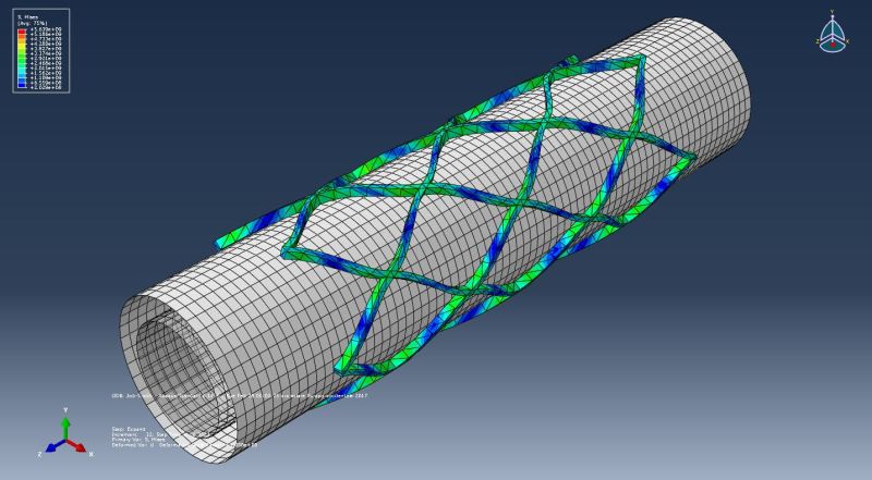
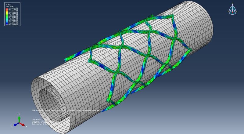
stent_open_1_rba47i.jpg

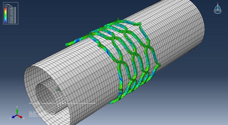
stent_open_2_btktfj.jpg

stent_open_3_egeyhi.jpg


As you see my stent during expansion it reduces its size in the z direction, changing frighteningly its length. This must not happen. The stent expansion must take place without changing the length of the stent.
How can I approach to solving the problem?

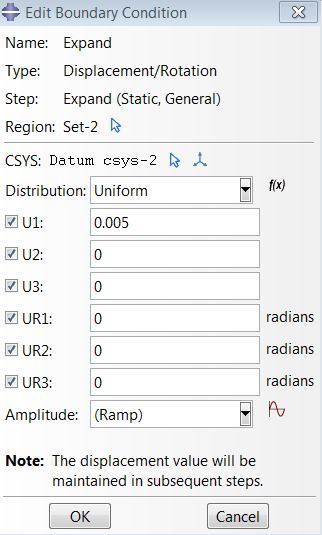
I've only Expand Step in which I've set a radial uniform Pressure Load and where BC's are:

bc_ygdxp9.jpg


Thank you
Luca
 
Stents will often shorten during expansion - the cells have to open up as the device expands and this results in a reduction in total length. This is typically referred to as "foreshortening". If you want to minimize foreshortening you will need to redesign your stent and adjust the size/geometry of the cells. In your case it looks like you are over-expanding your stent. Take a look at current commercial devices and you might get some ideas how to reduce foreshortening.

Also, reconsider the mesh on your stent. It's not great.
 
Perfect thanks.
Are you suggesting me to reduce the size of the mesh to make it more compliant expansion of the stent? During meshing I entered values for reduce calculation times ... but I'd have to see them again ...
How can I measure diameter of final expansion compare it with the initial diameter? There is a function for this in Abaqus?
 
I would use reduced-integration hex elements (C3D8R) instead of tet elements and I would increase the number of elements through the strut width and thickness. You might also want to refine the mesh near the crowns (this is where you will see peak stresses/strains). If you want to extract more accurate stresses/strains once you are happy that the model is working correctly, you can just switch from C3D8R to C3D8I elements.

If you want to measure the inner diameter you can probably just use the diameter of the expansion surface. If you want to measure the outer diameter you could just take measurements directly from the stent.


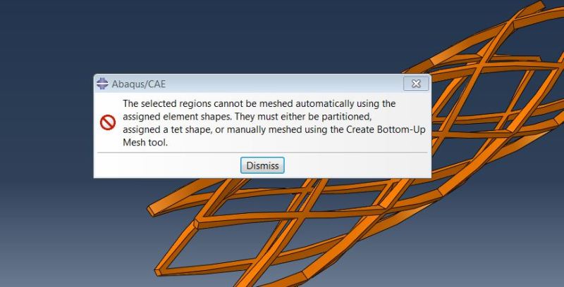
Yes, but when I try to assign Hex mesh this message appears

hex_smfhrb.jpg
 
As the error message says: If you want to mesh the geomtry with hex elements you will need to partition into multiple simple-shaped regions. This is described in the Abaqus User's manual. What a lot of people do to generate nice meshes for cylindrical devices like this is to draw the pattern flat in 2D and mesh using quad elements. Then you can extrude the mesh to give it thickness. Finally you can wrap the mesh into its cylindrical configuration using *NMAP.
 
Thanks for your reply.

If I understand you correctly you are suggesting me to design my stent in 2D with an external software (I use Rhinoceros and I have to continue using this software, I can not draw directly into Abaqus). Then I can export the 2D model of stent In Abaqus (.stp file?) and here I can mesh with hex and impose a thickness to my 2D model. At this point with the NMAP Abaqus function I can wrap my model to the cylinder. Did I get it right?
 
You can generate your geometry/mesh whatever way is easiest for you but yes that's what I was suggesting. Draw your pattern in 2D, partition into simple 4-sided shapes, mesh with quad elements, offset mesh to assign thickness and create solids then use *NMAP to wrap the mesh into the intended cylindrical shape.

See pages 63-64 of the following thesis:
 
Thank you.
What you're proposing is really useful to me. I'm trying to draw my cell stent in 2D and then apply mesh in Abaqus and wrap it around the cylinder with the NMAP command. I have another problem though.
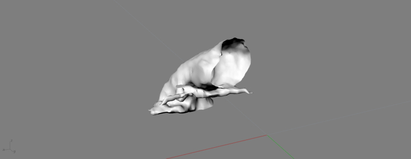
My stent addition to opening should also go to "bump" against the vein that, in my case, is represented by a .stl file that comes directly from the patient's radiological images. My surface is this:
pulmonary_vein_jyxzqt.jpg


How can I import it in Abaqus and make it interact with my stent? I tried .stl import but does not work.
Thank you again.
 
There are free converters available to convert your STL to a STEP. Otherwise, if you have access to an advanced CAD tool, you can do it straight from that tool (e.g., SolidWorks). Then, you can import the STEP file in the Part module.

You will have to specify an interaction property between the stent and the vessel. Vessel will also have to be specified with some mean pressure, I'd imagine.

Simulia Learning Community has an excellent best practices document that is worth looking into.

*********************************************************
Are you new to this forum? If so, please read these FAQs:

 
Hi IceBreakerSours, I use Rhinoceros that has a function to convert mesh to NURBS but what you get is a gross surface approximated by triangles and not a single compact surface. Practically this is a Reverse Engeneering process that would be very complex and long to do by hand. I haven't solidoworks. Have you experience about import of anatomical parts in ABAQUS in .stl format for simulation as what should I do? Do you think that if I import a .step file that comes from a .stl file will then be easier to manage this file in Abaqus (Part)?
 
Dave442 said:
I would use reduced-integration hex elements (C3D8R) instead of tet elements and I would increase the number of elements through the strut width and thickness. You might also want to refine the mesh near the crowns (this is where you will see peak stresses/strains). If you want to extract more accurate stresses/strains once you are happy that the model is working correctly, you can just switch from C3D8R to C3D8I elements.

Hi Dave, I re-open this thread because I need to ask you a question.
If I'm not interested in using the FEA simulation to optimize the stent geometry but only to verify the fitting between the stent and artery it is necessary however that I use Hex Elements instead of tet elements?
Thanks
Luca
 
you can use whatever elements you like.

Your stent geometry looks very simple to partition and hex mesh and your analyses would run quicker. If you are just interested in the deformed geometry of the stent I would still perform a mesh refinement study to ensure that your final geometry does not change by too much - the mesh you showed in your earlier posts looks extremely coarse.

 
There are trade-offs here.

Assuming you want be good at computational FE analyses, and aside from your immediate requirements, hex meshing is an art you want to become good at for many reasons. It takes a lot of practice to "simplify" a geometry, subdivide it, and then mesh it just so that the ultimate stress field is orthogonal to the "flow" of the mesh - all in the name of quality work. This is a cost you pay up front in the life cycle of a model. If you'd rather use automeshing capabilities and start churning out data quickly, then the cost will very likely accumulate at the back end when you refine the mesh with other kinds of elements.

If a model is just for a quick demo of the possibilities, the results are not going to be consumed to make any design decisions, and the turn-around time is short, then the latter approach may very well be reasonable. However, as a practice, I take as much time up front as I can to generate a high "quality" mesh.

*********************************************************
Are you new to this forum? If so, please read these FAQs:

 
Status
Not open for further replies.

Part and Inventory Search

Sponsor