Eng-Tips is the largest engineering community on the Internet

Intelligent Work Forums for Engineering Professionals

Step/touch potentials inside the ground grid Vs at the edges

Status
Not open for further replies.

NickParker

Electrical
Sep 1, 2017
396
0
16
NL
What is the difference between step/touch potentials inside the ground grid Vs at the edges of the ground grid?
 
Replies continue below

Recommended for you

Inside the ground grid would be NESC, and outside is NEC. The grid is ideally at an equal potential, so little step and tough potential. But outside it would be expected to be a much lower potential difference between points naturally. So grounding is specified as a single point ground (one ground point), and no touch difference.
The ground grid should extend to about three feet outside the substation, and the potential should drop off as you get more distance from the substation. The three feet is longer than most people can reach, so by the time you are off the ground grid, you should not be able to touch anything that is part of the substation.
 
In IEEE 80/2013 16.1 Design criteria is written:
“For equally spaced ground grids, the mesh voltage will increase along meshes from the center to the corner of the grid. The rate of this increase will depend on the size of the grid, number and location of ground rods, spacing of parallel conductors, diameter and depth of the conductors, and the resistivity profile of the soil. In a computer study of three typical ground grids in uniform soil resistivity, the data shown in Table 11 were obtained.”

 
 https://files.engineering.com/getfile.aspx?folder=3139c35f-84e0-4acf-8833-ed176d4a3fb2&file=IEEE_80_Table_11.jpg
Conceptually they are the same inside and outside the fenceline, but do elaborate if you had something specific in mind.
For a touch voltage, as Cranky108 mentions, you have to be within reach of something to touch. Inside the station there is more equipment to make contact with while outside you may just have the fence (and swing of the fence gates if then extend outward).

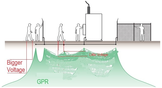
Typically your maximum step voltages occur right at the edge of the ground grid, think of the GPR as a plateau and if one foot is on the fence ground loop and the other is off the 'cliff' that is a big step potential.
Other considerations are:
-surface cover layer (crushed rock may not extend outside the station more than 3') resulting in difference IEEE 80 compliance criteria
-most grounding studies focus on the substation and associated equipment... but there are possibility of transferred voltages outside the station where someone may experience a shock from a pipe.

Next Wednesday there is an XGSLab/EasyPower Grounding Workshop that is free two hour webinar.
 
DBL-E said:
Conceptually they are the same inside and outside the fenceline, but do elaborate if you had something specific in mind.
That's what I understood until I read this article,
step_potential_at_the_periphery_eckrg4.jpg
 
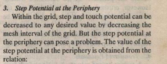
The reason step potential at the periphery can pose a problem is because there are no more meshes outside the periphery. You can't decrease the mesh interval if there are no meshes.
 
Transfer potential is a concern, so in reality no conducting materials, other than lines, should be extending from the substation. Communications are usually where such a concern happens, which in many modern substations happens by fiber, which is non-conductive, as is the plastic conduit.
But be careful of maintenance and construction people who may extend an extension cord from the substation outside for reasons. That maybe a risk that should be flagged. Many of these people don't see the risk, and may downplay it if they do know.
Other things I have seen is water or gas pipe. Water pipe used for irrigation, should not be within the three foot boundary of the ground grid and no restroom facilities should be on the substation property (use portable facilities outside the fence).
Gas pipes for generators is a concern, outside of generating facilities. It is better to use propane.
 
not really much you can do about step potentials at the periphery other than spending needless money to lower the overall GPR below the tolerated step potential.
 
As Jghrist mentioned, you can increase the mesh outside the property line, (you can see the person walking on the edge is near the 'drop off' of the GPR, while within the substation you can add another conductor to make the soil voltage closer to the GPR of the ground grid.

Step_Voltage_Off_the_Mesh_sy63di.jpg


At the periphery, IF you have step issues then you can look into-
[ul]
[li]Surfacing (but this need maintenance)[/li]
[li]angled rods to reduce that 'drop off'[/li]
[li]Deeper ground loop, again to reduce the pitch of the 'drop off'[/li]
[/ul]
 
cranky108 said:
Transfer potential is a concern, so in reality no conducting materials, other than lines, should be extending from the substation.
But the lines themselves extend neutral conductors outside the substation and are connected to ground wires running down poles that are exposed to the public. Does this cause a transfer potential problem?
 
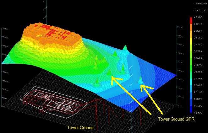
yes, in North America and other regions we use a multi-grounded neutral for distribution, and many areas have shield wires providing a metallic connection from the substation grid to the tower grounds. With that metallic connection you would see a transferred voltage that exposes the public to shock hazard (I made more graphs with paint to annotate)

GPR_at_TowerGround_gm2joq.jpg


In Australia they seem to consider a risk based method to evaluate if tower/pole grounds should have an analysis like we do for substations. I believe it is common to study tower's that are joint use with telecom as well... but I think there is more work to determine the risks and where to do detailed studies for mitigating hazards. In the substation's we know we have personnel performing maintenance so its industry standard to design an engineered system to protect from touch/step.
 
In the US the shield is typically steel, where the neutral is typically ACSR, which can transfer the potential, but you would be transferring the potential some 20 to 30 feet from the substation, so the only tough with a good ground would be the pole ground. And in some places the pole ground is covered (wonder why they don't do that everywhere?).
 
Come to think of it, years ago it was a common practice to cover pole grounds with a half round piece of wood, that was stapled into place. Why was this, and did it help touch potentials?
 
Analyzing touch- and step-voltages around pole grounds is not simple. The voltages are a result of current flowing through the earth at the pole ground. For a fault in the substation, the amount of current flowing through the earth at the pole ground depends on the split of fault current between the substation grid and all shield wires and neutrals. The amount of current in any one pole ground depends on the impedance of the neutral and the mutual impedance between the neutral and earth for the whole feeder.

Each feeder is different and pole grounds can be close to a lot of different buried objects like pipes that influence the voltages. You also have secondary and service neutrals that are connected to the multi-grounded neutral.

The transferred potential problem for a fault in the substation is only one concern. You also can get touch- and step-voltages around pole grounds for faults on the feeder where some of the return current flows through the earth.
 
Cranky said:
Come to think of it, years ago it was a common practice to cover pole grounds with a half round piece of wood, that was stapled into place. Why was this, and did it help touch potentials?

Yes. Plastic coverings are used now. A ground rod disconnection might cause a touch potential hazard otherwise.
 
We only use pole ground mouldings on poles in certain areas of our system that is more prone to copper theft. Its like putting a lock on something, a dishonest man that steals will cut the lock. In our case, remove the moulding.
Copper clad steel is a better deterrent. Harder to cut and has no real value at a scrapyard.
 
Status
Not open for further replies.
Back
Top