Continue to Site

Eng-Tips is the largest engineering community on the Internet

Intelligent Work Forums for Engineering Professionals

  • Congratulations KootK on being selected by the Eng-Tips community for having the most helpful posts in the forums last week. Way to Go!

Stiffener Arrangement for the Vessel and saddle.

Status
Not open for further replies.

MOHAMMED89

Mechanical
Feb 25, 2015
85
I want to modify an existing vessel, Vessel Length 10m (T/T) And Dia 3.5m.

Saddle analysis is failing since the bending stress at the horn of saddle is failing for the operating case.

I have checked in in the Dennis-R-Moss, And is mentioned that stiffener can be provided to reduce the bending stress.

So i have run the PVElite calculation by proving the stiffener, Now the calculation is passing but i would like to know that the stiffener arrangement as per the attached sketch is acceptable or not.
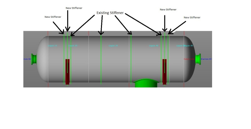
CaptureNew_zcpvam.jpg
 
Replies continue below

Recommended for you

Have you the ASME VIII div.1?

Regards
r6155
 
Dear r6155,

yes the design code for the vessel is ASME Sec. VIII. Div. 1
 
Last I saw, ASME VIII-1 did not limit (or even discuss) the location of stiffeners for saddles (Div 2 may as it addresses design of the saddles). The Zick saddle design paper restricts the maximum distance of the ring from the saddle centerline to no more than R/2 (R is the shell radius). The stress distribution in the shell and rings will vary as the distance of the ring(s) from the saddle vary.
 
Looks like a lot of stiffeners, but I see nothing wrong with it.

Regards,

Mike

The problem with sloppy work is that the supply FAR EXCEEDS the demand
 
Can you tell us: shell thickness and material, distance between saddles, width of saddles, design pressure and temperature, corrosion allowance, dimensions of rings, design total weigh, type of heads?

Regards
r6155
 
SnTMan said:
Looks like a lot of stiffeners, but I see nothing wrong with it.

I agree that it's unlikely to need "3" stiffeners at each saddle (the existing one plus the two new ones), and may even be counterproductive in some ways.

The existing set of 4 rings are likely for vacuum design. However, the two rings that are immediately adjacent to the saddles could likely act as saddle stiffener rings as well. It's possible that the original design did not consider these for the saddles. So you may wish to check the saddle analysis using the one existing stiffener ring. If the analysis fails then add 1 more ring (either at the saddle centerline or outside the saddle).

 
I think this is a follow-up from an earlier thread: Link

If so, this is an existing vessel that is being re-rated, and the calculations were showing failure of the existing saddle design at the horns. Not knowing anything else about the design, I had recommended adding a stiffener ring integral with the saddle. Now we are getting more information that there are already some existing vacuum rings...

I agree with Mike, it's unusual but I see nothing wrong with the proposed design. I suspect however that you don't need to be adding the extra stiffeners between the saddles and the heads. You could probably get away with only adding the stiffener to the saddle.
 
Dear r6155, details provided below:-

shell thickness and material - SA 516 Gr. 65 - 14mm thk.
distance between saddles - 7150mm.
width of saddles - 230mm.
design pressure - Internal 3.5bar / External 1.05 bar
Design Temperature - Internal 200degC / Outside 80degC.
corrosion allowance - 4.5mm
dimensions of rings - Vaccum ring (existing) thk. 15, width 130mm.
New saddle stiffener - thk. 15, width 230mm.
design total weigh approx. - Empty 30 Ton, Test weight 140 Ton
vessel head - 2:1 Ellipsoidal.

Dear TomBarsh, SnTMan, marty007 - Thanks alot for your valuable inputs and advices.

However, i tried the calculation again with stiffener arrangement recommented above. But the saddle still failing. Hence I would like to know whether we can provide one new saddle to this vessel. So the total saddle will be three numbers.

I have checked in different books and codes but no where i found three saddle arrangement. Can anyone please shared some light on this.
 
The design of triple saddle supports is problematic.

If you go back to the basic theory of static forces, a three saddle support is an indeterminate problem. You can't solve for the load on each saddle with simple force and moment diagrams. To solve such a problem, you would actually have to get into details of material flexibility and displacement. A better comparison would be to piping stress analysis methods, where you can have many different supports acting on a single pipe run.

Needless to say, this gets ugly, and is why 99% of vessels are supported on two saddles.

That's about as much as I know on the topic, as I've only ever had to explain this issue to this extent to convince people to change their minds... I don't know of any design guides that are applicable to vessels, but if anyone else has one I'd be very interested. I suspect this type of design might come down to FEA methods rather than hand calculations.

Cheers,
 
The vessel on 3 (or more) supports is a statically indeterminate beam. This sort of problem is addressed in basic texts on strength of materials. The analysis doesn't present any grave difficulty for solution (but please don't ask me to do so by hand, it's been over 35 years).

The larger concern I see is the possibility of differential settlement of the saddles, or even assuring that in the new condition that the saddles are all level and are "loaded" as the stress analysis assumes. Should the foundations settle slightly the assumed loading will be off and the resulting stress condition may be much more severe.
 
To pass the saddle design, provide full pad around the Vessel covering saddle wear plate + a flat ring from saddle horn (as an extension of the saddle vertical rib)around the vessel. Three flat ring stiffeners surrounding the saddle is not a good proposition.

For vacuum design provide additional flat ring stiffeners around the vessel with number and distance to suit the design.

All attachment welding shall be CFW of 0.7 x thick of pad or flat ring, with 100% LPT.

FEA may not be necessary as all the features are with in Code calculations.
 
1)IMO corrosion allowance (CA) 4,5 mm is excessive (aprox 6.000 kg)
2)If CA = 1mm additional stiffening rings is not required
3)Internal surface protection may be an alternative.
4)Try again with your calculation.

Regards
r6155
 
Status
Not open for further replies.

Part and Inventory Search

Sponsor