Eng-Tips is the largest engineering community on the Internet

Intelligent Work Forums for Engineering Professionals

Stiffness Matrix/ Solving for Displacements Problem 3

Status
Not open for further replies.

DJL Eng

Mechanical
Nov 9, 2023
14
0
1
US
I apologize in advance since this might be more of a math problem. I'm trying to learn FEA and I'm going through the first example problem from the "Practical Stress Analysis with Finite Elements" book by Bryan Mac Donald. Here is the problem:
P_20240620_222857_-_Copy_fyfdmt.jpg


I don't get how we can just take the first line/ equation out of the matrix. Though if we don't we end up with a 0 determinant matrix, and the system cannot be solved.
I am a bit rusty in my math, so I'm probably missing something. Any feedback is appreciated!
 
Replies continue below

Recommended for you

what they are saying is with zero on the LHS of equation 1 and zero on the RHS, then equation 1 doesn't help us solve anything.
there are three equations (rows 2,3,4) and 3 unknowns, so solvable. yes ? clear as mud ??

"Hoffen wir mal, dass alles gut geht !"
General Paulus, Nov 1942, outside Stalingrad after the launch of Operation Uranus.
 
Thanks for the reply rb! That's a clear explanation. I guess I am still struggling on the math part.

If I multiply out the first equation, I get 1*10^8*(4.546*0 - 4.546*U_2 + 0*U_3 + 0*U_4) = 0 or U_2=0. Did I completely flub that one? Intuitively, my answer does not make sense because node 2 is unconstrained and element 1 is not infinitely stiff.
 
no, the math looks right. U2 can still be zero, if the applied loads are not exciting that freedom. For example there is no lateral deflection in a typical SS beam with vertical loads. If there is an inclined load then the lateral deflections get excited.

"Hoffen wir mal, dass alles gut geht !"
General Paulus, Nov 1942, outside Stalingrad after the launch of Operation Uranus.
 
The problem setting is odd in my opinion. For a hand calculation, one would enforce the constraint by setting to zero the relevant row of the stiffness matrix (in this case, the first row, since the constrained dof is U1), then setting the term related to the relevant DOF to one (in this case, term 11 of the 4x4 stiffness matrix (11 = row 1, column 1)), and then setting the force vector equal to the prescribed value (zero in this case).

Alternatively, you can eliminate constrained degrees of freedom before assembling element contributions.
 
who knows, other than the OP ?

reading it again they say node1 is attached to the wall so U1 is zero. Why does it follow that F1 is zero ? unless you know there is no load applied in that direction (either directly or indirectly (consider a two element truss with a vertical load, and a vertical reaction and a couple ... ie reactions in a direction where no load is applied.

"Hoffen wir mal, dass alles gut geht !"
General Paulus, Nov 1942, outside Stalingrad after the launch of Operation Uranus.
 
"Why does it follow that F1 is zero ? unless you know there is no load applied in that direction (either directly or indirectly (consider a two element truss with a vertical load, and a vertical reaction and a couple ... ie reactions in a direction where no load is applied. "

The reaction is nonzero, but that is not related to how the equation system is solved for the unknowns U2, U3, U4. Setting the load vector term to the prescribed numerical DOF value and setting the row of the stiffness matrix to zero (except for the term related to the DOF) is a standard method for solving the unknown DOF, at least for linear static problems. More efficient schemes can be used for computer implementations where symmetry is desired.
 
why isn't F1 -10000N ? u1 is zero (because it is attached to the wall). Because it is attached to the wall it is reacting the applied load, no?

but then how to make sense of the 1st equation, the first row. There is no work done by this reaction, as displacement is zero; ok
Going back to equation 1.17 (pg20), ok, K*x = f ... but we know the force applied on node 2 is 10000N (why 0? ok, there is no "external" force applied and maybe the impact of the external force on node 4 will be transferred here by the matrix math ??) but we can easily calculate the displacement of node 2 (u2) and this displacement affects element 2 (and node 3) but doesn't cause any strain energy in element 2 ...

this is IMHO a terrible 1st example (I assume) model. I would have started with simple truss models.

"Hoffen wir mal, dass alles gut geht !"
General Paulus, Nov 1942, outside Stalingrad after the launch of Operation Uranus.
 
As stated by others, the force at the first node is not zero, it is -10,000 N. The reaction force is every bit as much an external force as the applied force at the other end. If you multiply out the matrix equation with the given displacements it gives the correct result:
Engtips24Jun24-1_qxrl6t.jpg


But if you add an equal displacement to all the nodes, the forces remain unchanged:
Engtips24Jun24-2_mmasdn.jpg


That is why the 4x4 matrix can't be solved, there are infinitely many valid solutions.

Fortunately we know the deflection of node 1 is zero, so we can remove the top row and left hand column, and solve the remaining 3x3 matrix, to find the relative deflection of nodes 2-4.
Engtips24Jun24-3_g1zjeq.jpg


Doug Jenkins
Interactive Design Services
 
I appreciate you doing/showing the work IDS! I agree that there should be a reaction at the wall. I guess I also failed to realize we could remove rows/columns once we know nodal constraints. All that said, I might just punt this book to the side and use a different reference to learn FEA. Throughout the first chapter, leading up to this example, there were enough errors/ inconsistencies to lower my confidence in this textbook.

Thanks everyone for taking the time to help me out with this. I can sleep better tonight.
 
Showing centondollar's method were rather than remove the row and column associated with the restrained degree of freedom instead replace just the row with the identity row and use a fictitious 0 force this allows the whole matrix to be inverted. I have some older textbooks where this method was common rather than partitioning of the stiffness matrix which I believe is the much more common approach these days.

Screenshot_2024-06-24_102627_skk6ru.jpg


edit: the field labeled dummy reaction should be more clear that it is required to be 0, otherwise the first term in the second row will start to influence the resulting deflections.
 
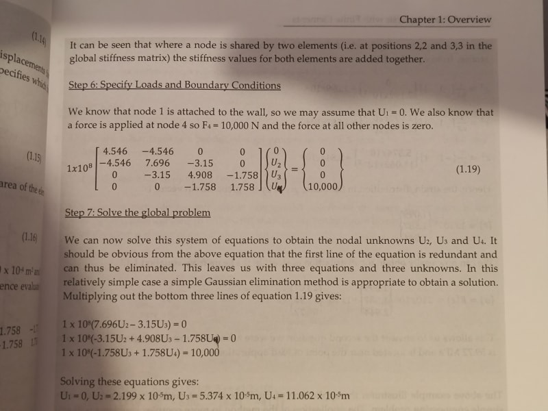
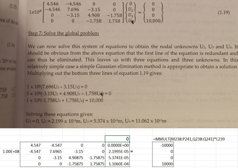
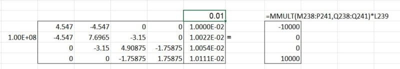
the general solution is the full 4 rows ... [k]*d = F

then fill in the known parts of the solution ... d(1) = 0, F(1) = -10000, F(4) = 10000
then solve for d(2), d(3), and d(4).

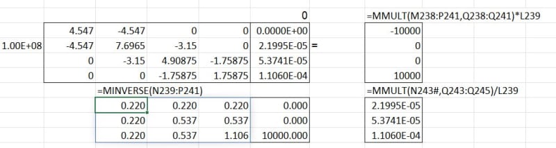
Reducing the 4x4 matrix to a 3x3 seems to give the right answer (although as noted above, it doesn't give a complete solution for 4 variables), but it overlooks the point you made to my initial post, "what about k(1,2)*d(2)=F(1) ?" which is the missing piece of the puzzle (and it seems that the right solution has this "baked" in).

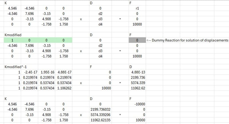
I don't think the text is Wrong, but is somewhat torturous in it's logic, and missing explanation, and obfuscating a very simple problem. Missing that F(1) is -10000 is basic ... and I don't think you need it to solve d(2), d(3), d(4) (as the 3x3 matrix shows) so you can have F(1) = F(1) (an unknown force) initially and solve k(1,2)*d(2) = F(1) to finish the problem. This is how FEA codes work ... they reorder the equations (the rows of the matrix) so that the reactions (with zero displacements) are together and then they solve the rest of the structure (the 3x3 in this case), and then they solve the reactions (ie k(1,2)*d(2) = F(1)). In this case we can look at the problem and say F(1) = -10000 but in a general problem we can't (or not as easily). IMHO this is a better way to present the solution of this problem, more closely following the general FEA method, without inserting data we know. As you observed, in this simple problem we know F(1) = -10000, and this tells us what d(2) is so only d(3) and d(4) need to be found. More generally we don't know F(1) so it should be a variable, we know d(1) is 0 and F(4) = 10000 (and F(2) and F(3) = 0) and we can use the 4x4 matrix to determine the unknowns ... d(2), d(3), d(4), F(1) ... 4 equations, 4 unknowns.

"Hoffen wir mal, dass alles gut geht !"
General Paulus, Nov 1942, outside Stalingrad after the launch of Operation Uranus.
 
I think the different approaches to this are quite interesting, and thanks to Celt83 for the detailed description of how the modified K approach works.

That said, I don't think that approach is helpful in looking at how FEA works for more complex systems, since it requires a magical node that doesn't move when a force is applied, but somehow doesn't have a reaction force.

The answer to the question in the OP is that since the deflection of Node 1 is known to be zero, we don't need to include node 1 in the simultaneous equations, as stated by rb1957 in his first post.

The three required equations are extracted from the 4x4 matrix, which is equivalent to removing the first row and first column. The 4x4 matrix isn't modified, the required data is extracted from it to form a 3x3 matrix, which is all we need to find the three unknown deflections. The 4x4 stiffness matrix can then be multiplied by the displacement vector to find the net force at each node, which is -10,000 N at Node 1.

That is basically what the text in the book says. The only misleading part is showing the force at Node 1 as zero, which is in my opinion just wrong.


Doug Jenkins
Interactive Design Services
 
IDS: the removal of rows and columns is as far as I know accomplished by modifying the force vector (extracting appropriate multiples of stiffness coefficient and enforced constraints) in numerical algorithms. If the BC is a zero DOF, the procedure reduces to zeroing out the relevant rows and columns, setting the stiffness matrix diagonal term to one (e.g., k22 for DOF u2), and applying the constraint value to the row in the force vector.

Identifying a relevant subset of the stiffness matrix and force vector is of course suitable for hand calculation, and for hand calculations, it is easy to do the reduction before assembling the global system.
 
centodollar - the standard procedure I am familiar with is:
- Allocate an index number to every unrestrained degree of freedom in the model.
- Form the global stiffness matrix for the unrestrained freedoms.
- Form the matrix of applied loads for each unrestrained freedom.
- Solve the system to find the deflections
- Apply the deflections to the ends of each member to find the member end actions, including the reactions at restrained nodes.

That is essentially what is done in the text in the opening post, except they form the global matrix including the restrained freedom first.

The only problem with it that I see is that they show the force at Node 1 as 0 rather than the reaction force, which is the problem raised in the OP.

Doug Jenkins
Interactive Design Services
 
maybe it's just words but as I say "words have meaning", and what's a technical discussion without semantics ?

we're not removing rows ... we're partitioning the matrix in ways that make sense and make the solution solvable.

In this case, we know d(1) is 0 and whilst we know F(1) = -10000 that is only because the problem is so simple, generally we don't know the reactions. So if we know d(1) it makes sense to solve the other 3 equations to determine the other 3 unknown displacements; and when we solve d(2) and substitute into the 1st equation we get F(1) = -10000.

So we are partitioning the stiffness matrix into two pieces ... one with unknown displacements, the other with unknown forces.

"Hoffen wir mal, dass alles gut geht !"
General Paulus, Nov 1942, outside Stalingrad after the launch of Operation Uranus.
 
Status
Not open for further replies.
Back
Top