Continue to Site

Eng-Tips is the largest engineering community on the Internet

Intelligent Work Forums for Engineering Professionals

  • Congratulations IDS on being selected by the Eng-Tips community for having the most helpful posts in the forums last week. Way to Go!

Stiffness

Status
Not open for further replies.

zonaguy920

Mechanical
Apr 16, 2017
10
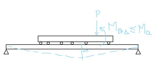
Assume a beam with attached rollers (top beam, see attachment) is being supported by another beam that is simply supported (bottom beam). I want to ensure the top beam does not get overstressed due to bending because the bottom beam is not stiff enough. Is it enough to assume that the EI value of the bottom beam just needs to be greater than the EI value of the top beam? If not, looking for guidance on the proper approach. Thanks
 
 https://files.engineering.com/getfile.aspx?folder=8a497c63-644a-451e-a9b9-9bbe40e85866&file=2_stacked_beams.jpg
Replies continue below

Recommended for you

It's not quite that simple, as you suspected. If the bottom beam is much stiffer, say 10x, then it's effect on the reactions and hence the bending of the top beam will be negligible. You could analyze the top beam with the roller supports at each location and be within a few percent of correct.

If the bottom beam is of similar stiffness, then the top beam will have a bending diagram in between the previous case and a simple span from end to end. Where in between? Hard to say (and also dependent on the span lengths, I think).

What exactly is the ratio of stiffness to neglect the bottom beam? It depends what margin of error your top beam can handle, but my guess would be between 5x and 10x.

----
just call me Lo.
 
The rollers are not uniformly spaced, but they are frequent enough to assume a uniform load under the top beam if the bottom beam is infinitely stiff.

There are two extreme cases:
1. The top beam is stiff enough to span its full length without relying on the bottom beam.
2. The top beam is not very stiff and relies on the bottom beam for full support.

The actual situation is somewhere between the extreme cases.

If the bottom beam is designed to support all load on the top beam and it satisfies deflection criteria, the top beam cannot be over-stressed because at worst, it bends to the same configuration as the bottom beam; at best, it supports a portion of load which it is capable of sustaining, thus reducing the moment in the bottom beam.

To find the exact answer, compatible deflections could be determined.

BA
 
You have to first determine the load pattern that will produce the maximum moment in the top beam, then set aside a portion for moment induced by support settlement, which is a function of the lower beam deflection. Without setting the tolerance for moment induced by the deflection, the rigidity of the lower beam needs to be infinite large (Δ = 0).

image_pzkhit.png
 
This is the thread for you: Link

The theory is neat, if rather complex. If you're looking to solve a real world problem, we can probably simplify that a fair bit with some additional detail:

1) Will the rollers be in definite, stationary locations?

2) Will there be a physical air gap between the upper and lower beams between rollers?

3) Will all loads be applied to the upper beam?
 
zonaguy920,

If your top beam needs to be rigid, make it strong and rigid, and don't worry about the beam underneath (too much). If you are relying on the bottom beam for the strength and rigidity, then your only concern about the top beam is that it withstands crushing. It is like a coat of paint.

Your composite structure is complicated, and it will fail when somebody modifies it, not knowing what you are doing.

Note how your top beam cannot possibly work unless the bottom beam is significantly more rigid.

--
JHG
 
zonagaguy,

The top beam shall be a stable structure in order to get a meaningful solution. At this moment, the top beam will roll freely.
 
Simplest solution...design top beam to carry all of the load on its short span. Design the bottom beam to carry the end reactions plus any additional load applied to the bottom beam beyond the short top beam.

BA
 
Analyse the system with some compression only elements at the roller locations, loading each beam with any applied loads. Play with stiffnesses until it works or you are happy with the way the loads are really shared.
 
My conclusion from the discussion that Kootk linked to was that if the top beam was sufficiently stiff it would transfer all the load to its ends, so the moment in the lower beam would be significantly reduced, or if not all the load would in effect be transferred straight to the lower beam at midspan. Not everyone agreed with that, but I didn't see any convincing arguments against it.

With the rollers, this would suggest that the load would either be transferred through the two end rollers with a stiff upper beam, or the two closest to the centre otherwise.


Doug Jenkins
Interactive Design Services
 
Status
Not open for further replies.

Part and Inventory Search

Sponsor