Continue to Site

Eng-Tips is the largest engineering community on the Internet

Intelligent Work Forums for Engineering Professionals

  • Congratulations SDETERS on being selected by the Eng-Tips community for having the most helpful posts in the forums last week. Way to Go!

Stiffness?

Status
Not open for further replies.

MIStructE_IRE

Structural
Sep 23, 2018
816
Hi there,

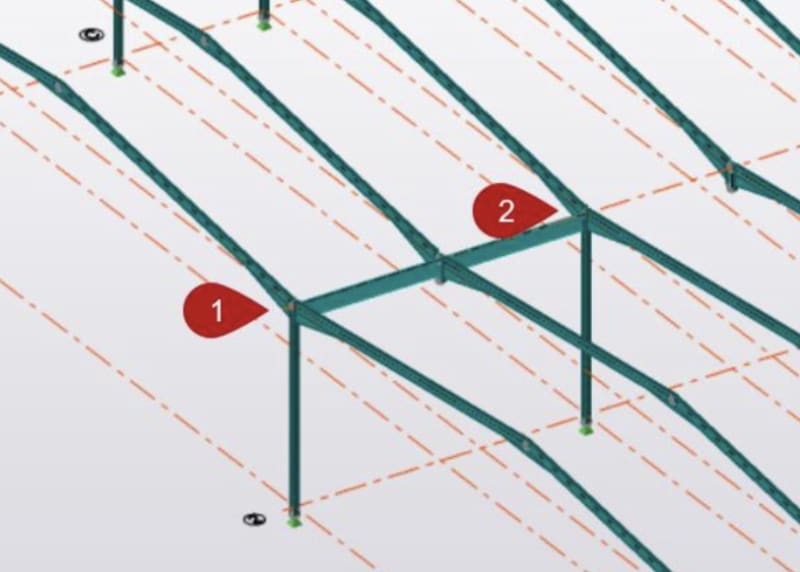
I’m looking at a hit and miss portal frame as you see below and I need to calculate the stiffness of the beam spanning between points 1 & 2 to input into the frame design software.

The stiffness is to be input as kNm/rad - and my old statics teacher would kill me if he’d seen me forget this one! Can anyone assist?
21652D08-16CD-4EFE-9B3E-206737A1D896_igf2xj.jpg
 
Replies continue below

Recommended for you

That doesn't make any sense. That's a torsional stiffness unit, not a bending stiffness.
 
Here’s an extract from the software’s worked example - only they don’t show how they’ve calculated this.

If I go with 48EI/L^3 then I don’t get anything like the values they’ve used.

F222EA65-DBC7-4FCA-9EF9-574BB41F40AA_ed0tmh.jpg
 
Interesting, I've never seen that before as a beam stiffness value. Hopefully someone in the know can come along and inform us.
 
That software "worked example" is complete nonsense. Beam (bending) stiffness has units "Force*length^2", e.g., "Nm^2", while beam axial siffness has units "Force/area" and beam torsional stiffness has units "Force*length/radian".

What they might be referring to (don´t quote me on this) is the stiffness of the beam-to-column connection, given as a rotational spring stiffness. Rotational springs have units "Moment/radians", e.g., "kNm/rad". However, since the word "free rotationally" is used after mentioning two rotational stiffness values, I suspect that the person who wrote that example does not understand basic structural mechanics.

To answer your question: the beam stiffness is not input into the software as "kNm/rad" - that is a rotational stiffness at a joint. The beam (bending) stiffness is automatically calculated from the sectional properties of the modeled beams (Young´s modulus and the 2nd moment of area determine the bending stiffness); axial and torsional beam stiffness is also automatically defined by the software.
 
Thanks guys,

It appears that this is in fact a typo in the manual! When I go into the actual software itself, the vertical stiffness is to be input as kN/m - which makes more sense.

Nonetheless, I’m still not getting 3,300kN/m for a 12m long 610 x 229 UB 101 beam.
 
The program treats this joint as spring support that consisted of the vertical (linear) spring, and rotational spring. The stiffness of the rotational spring is the moment required to rotate the joint by 1 rad. You can apply a dummy moment and divide it by the resulting rotation angle of the joint. Try the example problem first, see whether it works out or not.
 
Is the beam spanning between the centre columns simple supported at ends? If so, can you run a simple beam loaded with a point load at mid span and determine load for a unit displacement?

Rather than think climate change and the corona virus as science, think of it as the wrath of God. Feel any better?

-Dik
 
Instead of using a spring support to simulate the stiffness of the "valley" beam, why not just model the valley beam.
 
Status
Not open for further replies.

Part and Inventory Search

Sponsor