N.K.
Structural
- May 30, 2019
- 14
Hi All,
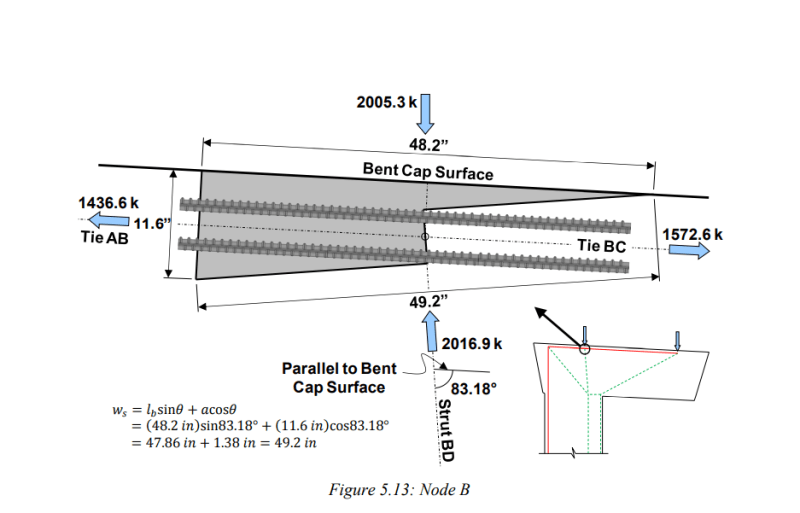
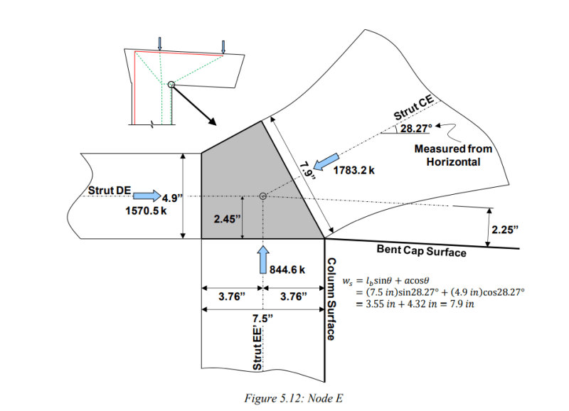
Does anyone know if some of the nodal geometries shown in the document 'strut and tie model design examples for bridges' complies with the Australian code. There are some geometries woth stepped nodal faces and nodal faces that are unstressed. To me this doesn't seem like an issue but I just want to make sure I haven't missed anything before applying these rules.
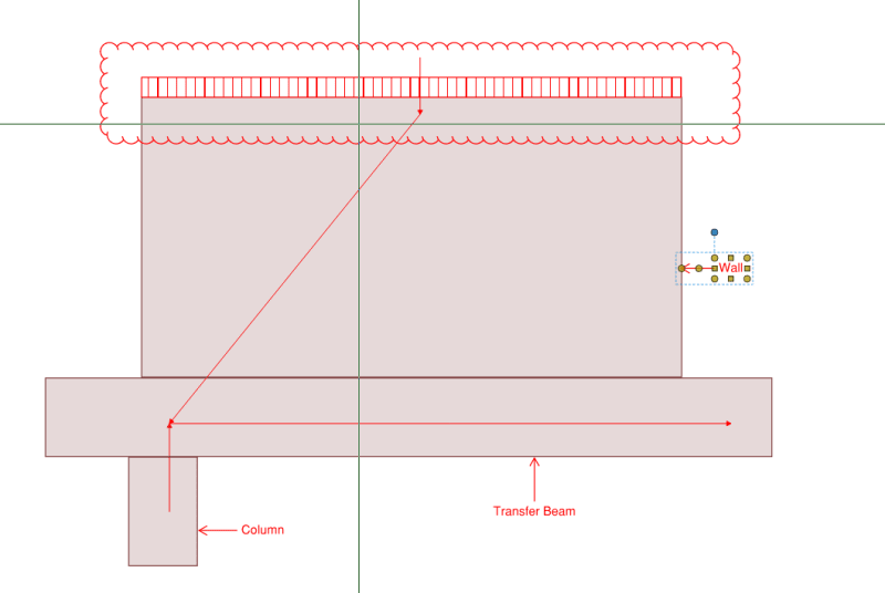
In addition to this. How can one define a nodal geometry for a UDL that is applied over a wide surface. Say for example the UDL on the top of a wall (STM to take the load to discrete support points).
I have so many questions and I can't seem to find answers.
Thanks!!


