Continue to Site

Eng-Tips is the largest engineering community on the Internet

Intelligent Work Forums for Engineering Professionals

  • Congratulations SSS148 on being selected by the Eng-Tips community for having the most helpful posts in the forums last week. Way to Go!

Story drift definition 2

Status
Not open for further replies.

ARKeng

Structural
Oct 8, 2004
51
We're having a discussion among several very experienced engineers in our office and now we're more bewildered that it has taken us this long to realize we have multiple definitions for the same term: STORY DRIFT. We're in seismic country so we have code-required drift limits.

ASCE 7-16 section 11.2 defines STORY DRIFT as follows:
STORY DRIFT: The horizontal deflection at the top of the story relative to the bottom of the story as determined in Section 12.8.6.

The question that is being debated is: Are diaphragm deflections supposed to be included in the story drift check? As far as we can see, there is no specification in ASCE 7 either way, despite some of those involved in the discussion being sure that there was (but on both opposing sides of the definition).

Before I weigh in with any arguments, I'd love to hear how everyone applies this.
 
Replies continue below

Recommended for you

No. But I would like to hear why you say "yes".
 
If I recall correctly, in ASCE 7-10 you take the average of the 2 corners, unless you have certain irregularities (don't remember which, torsion perhaps?), in which case you must take the worst case drift.

 
I have always taken story drift as the drift of any point on a floor relative to the same point on the floor below. See my diagram below.

Capture_mirvcg.png
 
I'll go ahead and start the arguments for/against but would still like for others to weigh in:

Arguments FOR including the diaphragm deflection
[ol 1]
[li] ASCE 7-16 11.2 definition: "STORY DRIFT: The horizontal deflection at the top of the story relative to the bottom of the story as determined in Section 12.8.6.[/li]It says "horizontal deflection"... why should we assume it only includes horizontal deflection of the vertical elements and not the deflection of the diaphragm?
[li]
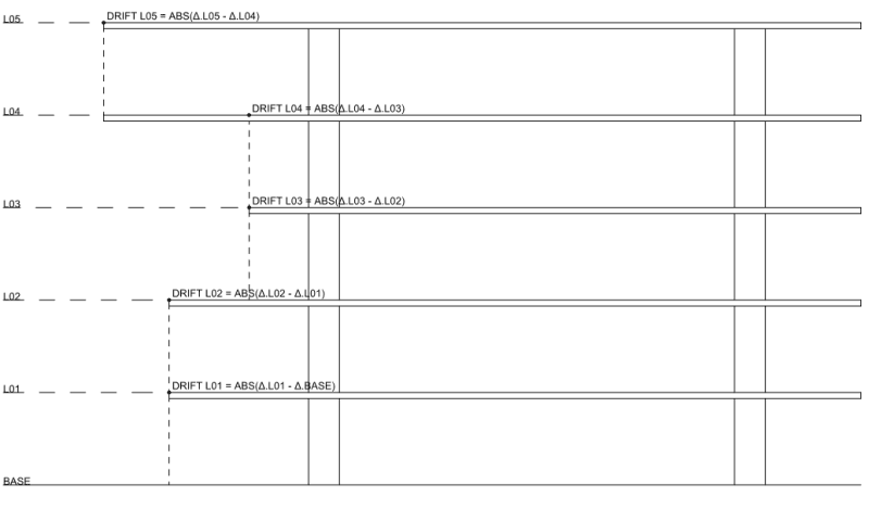
ASCE 7-16 12.8.6: "Story Drift Determination. The design story drift (Δ) shall be computed as the difference of the deflections at the centers of mass at the top and bottom of the story under consideration."and also...
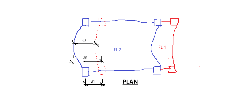
"the design story drift, Δ, shall be computed as the largest difference of the deflections of vertically aligned points at the top and bottom of the story under consideration along any of the edges of the structure."[/li] Wouldn't the center of mass of the a story diaphragm have diaphragm deflection included if it's in the middle of the diaphragm? Or for the other requirement, it doesn't only say "parallel to the edge", it says "along any of the edges"... "I can have significant diaphragm out-of-plane deflection at the midspan of my diaphragm at the edge of the structure"
[li] ASCE Figure 7-16 and section 12.3.1.3 introduces a term "ΔADVE" for the "average drift of vertical element". If this is the same as the story drift, why do they have two separate terms?[/li]
[li]"Nothing tells me I don't have to include it, so why wouldn't I?"[/li]
[li]What's the goal we're trying to achieve by limiting story drift? The general consensus seems to be the concern has to do with stability and P-delta effects on vertical gravity load-carrying elements (columns, bearing walls, etc) and limit damage/cracking of non-structural elements. Given that, what good is only paying attention to the drift right next to lateral elements if there's significant lateral movement in between? Where's the guidance on what's allowed if it's not limited with the story drift?[/li]
[li]"Not including it is dumb. You're saying I can put a really stiff shearwall at the center of mass and at the edges and everything else in between doesn't matter by code?"[/li]
[li]"Why would ASCE 7-16 Section 12.12 'Drift and Deformation' include 12.12.2 about Diaphragm Deflection? Clearly drift/deformations/displacements/deflection are pretty much being used interchangeably"[/li]
[li]Various examples that say it does... for example, page 45 of [URL unfurl="true"]https://www.woodworks.org/wp-content/uploads/design_examle-Design-Example-of-a-Cantilever-Wood-Diaphragm.pdf[/url]: says "Drift consists of three components: diaphragm translation and diaphragm rotations from wall displacements and in-plane diaphragm deformations, as shown in SDPWS Figure C4.2.5B. Drift ∆ =δTranslation+δRotation+ δDiaph
The deflection from translation and rotation are based on the response of the shear walls under the rigid diaphragm assumption"[/li]So this is for a cantilever diaphragm, so it's unclear if the same equation would apply to a normal simple span diaphragm, but why wouldn't it? The check given is at the maximum condition including the maximum effect of diaphragm deflection (rather than the center of mass as stipulated by code), so why wouldn't we be interested in the maximum condition in a simple span? I believe there are more examples others found yesterday too, will post later if I find them...
[/ol]

Arguments AGAINST including the diaphragm deflection
[ol 1]
[li]"Nothing tells me I have to include it, so why would I?"[/li]
[li]ASCE 7-16 Figure 12.8-2 seems to only be focused on frame deflection[/li]
[li]"Drift is only the vertical elements, not displacement. ASCE 12.8.4.3 talks about the average of "displacements" of the ends of the building. If that was the same as "drift" why use two different terms?"[/li]
[li]"Why would ASCE 7-16 Section 12.12.2 talk about Diaphragm Deflection limits on their own if they wanted it included in the drift?"[/li]
[li]"The story drift requirements include a Cd amplification factor on drift that is dependent on the vertical system. Why would the amplification on the diaphragm deflection be different for different vertical systems if they're the same diaphragm in two different structures?" (Response: because you already reduced the forces for R based on the vertical system, so they're basically make you undo that reduction."[/li]
[li]Internet sources like: [URL unfurl="true"]https://www.woodworks.org/wp-content/uploads/DE-Panelized-Roof-Seismic.pdf[/url] (interestingly also from woodworks) that in the example on page 32 says: "It is worth mentioning here that diaphragm deflection is not included when evaluating the story drift limits of aSCE 7-10 Section 12.12.1. These limitations on building drift were developed primarily for the classic flexible frame system with a rigid diaphragm to prevent excessive distortion within the plane of the frame or shear wall. in masonry and concrete tilt-up buildings, these vertical elements deflect very little in-plane, with the bulk of translation occurring at other elements. The story drift limits of the building code do not apply to the diaphragm deflection."[/li]
[li]SEAOC Blue Book article here: SEAOC BlueBook – Seismic Design Recommendations Tilt-up Buildings Mostly the entire page 14 can be summarized with "Story drift limits do not apply to diaphragm deflection."[/li][/ol]

So with these arguments in play, what does everyone think?
In terms of persuasiveness I tend to fall in the "for including it" until I saw the SEAOC source that I feel is tough to argue with since it's so boldly definitive...

The one thing I'm certain of is that the code should be much clearer on what they want.
 
Diaphragm deflection does not need to be included when checking against the allowable drift limits in Table 12.12-1. Although Section 12.8.6 requires that drift be determined at a point on the diaphragm (either at the center of mass or at the edge of the diaphragm where torsional irregularities are present), this is only meant to account for the effect of rigid body rotation of the diaphragm amplifying vertical element deflections. It is not meant to include deformations within the diaphragm itself.

Section 12.12.2 does address diaphragm deflection, but it essentially leaves the limit up to the designer by invoking the all-inclusive (and, at times, elusive) deformation compatibility requirement. I suggest including it for determining seismic separations, although the code doesn't strictly require this unless you have a member spanning across the separation (Section 12.12.4).

Additionally, there is a clue to be found in section 12.3.1.1. Take a look at condition c2, where each line of vertical elements must comply with the allowable story drift. If the vertical elements were allowed by deflect all the way up to the allowable drift, no additional diaphragm deflection would be permitted if the limit was meant include diaphragm deflections. But since this section is for flexible diaphragms, that clearly is not the intent.

You can also find some great discussion and guidance in this document (Link) which is quoted below:

"It is worth mentioning here that diaphragm deflection is not included when evaluating the story drift limits of ASCE 7-10 Section 12.12.1. These limitations on building drift were developed primarily for the classic flexible frame system with a rigid diaphragm to prevent excessive distortion within the plane of the frame or shear wall. In masonry and concrete tilt-up buildings, these vertical elements deflect very little in-plane, with the bulk of translation occurring at other elements. The story drift limits of the building code do not apply to the diaphragm deflection."

 
Thanks Deker... looks like you found at least one of the same sources. [smile]

I do like your "clue"/argument regarding 12.3.1.1.c.2 also.
 
The whole point of checking drift is to ensure the building frame skeleton is rigid enough to prevent large sway associated with lateral loads. Diaphragm is merely a messenger that delivers and passes the lateral loads to the vertical frame members, it drifts with the vertical frame, and has no capability of restricting the motion. Thus, the deflection of the diaphragm, though is caused by the same loads, is not a concern of story drift. Also, isn't the deflection of the diaphragm considered a "vertical displacement" in its own plane?
 
ARKeng,

Which one below (d1, d2, d3) is each group pointing to?

drift_xpfcyt.png
 
retired13:
Just to be clear I am correctly understanding the graphic. Here's my understanding of your three dimensions:
d1 = how far the columns move story-to-story (column here could be shearwall deflection also). The technical term I would have previously used to describe this would probably be the "drift of the vertical elements" (similar to the ΔADVE" for the "average drift of vertical element" term from ASCE 7.

d2 = the maximum movement of a point on FL2 relative to the same vertically aligned point on FL1. This is also what
rscassar seems to be showing above. I previously would have called this "story drift"... further discussion below.

d3 = the total absolute horizontal displacement of the worst point on FL2.

Until this past week, I would unflinchingly have said the story drift we are interested in with respect to code limits is depicted by "d2". To me, it was basically finding the "d3" of every point on FL2 and FL1, calculating a d3(FL2) - d3(FL1) for every location in plan view, and the worst case of any of these values is "d2" and I would have called this story drift. At the bottom story, d3 and d2 are the same thing.

Now, I seem to be interpreting from the SEAOC source that the code limit only applies to "d1".

This is odd to me because in terms of the worst case of what the gravity columns and non-structural elements experience, they see "d2" so that seems to me to be what the code would want to limit.

I would also say the SEAOC process seems convoluted. ASCE 7 gives only the vague requirement of 12.12.2 that limits the diaphragm deflection. SEAOC then basically says to use 12.8.7 to limit the P-Δ, but to essentially use your "d2" instead of using the story drift... If this is that the case, why not just use "d2" from the beginning as the defining limit?
 
We are just a thread apart.

You know well that the amount of story drift is used to evaluate the secondary effect of P-Δ, which is to be apply to the vertical member to magnify the applied force (Mdgn=M+MΔ), to obtain the desired level of resistance. Since P is right on top of the vertical member, how could it make sense if you measure and take Δ somewhere else, such as d2, or d3 in my sketch. Conservative is all right, but theoretically it does not make sense. Hope this helps.
 
I'm with Deker and retired13, I think the point of story drift is to look at the relative drive of a column or wall from Story n to story n+1. Specifically where the column or wall is part of the lateral resisting force in that direction.

Now, what if there is a gravity only column at the middle of the diaphragm that doesn't resist any lateral load. Is that included in "story drift"? I would say it is NOT. However, you are obligated to ensure that it can support it's gravity load under the additional expected diaphragm deflection. And, that the P-Delta effect is resisted (either directly by the gravity only column or by going through the diaphragm back to the lateral frames).
 
I agree 100% with what JoshPlumSE just posted but would add one other point.

The total deflection of any point along a diaphragm should be considered if there is an adjacent structure and you are determining the necessary width of an expansion joint.

 
Thanks to everyone for weighing in...I believe a good summary of the consensus is that:
1. Diaphragm deflection components are not included in story drift limits
2. Diaphragm deflections obviously have to be considered in issues regarding property line, building separation, etc.
3. The main code-limitation on diaphragm deflection from a structural strength perspective is the stability affects on other elements.

Related to note #3, and maybe this should be its own thread...

For evaluating diaphragm deflection effects on walls perpendicular to the diaphragm. Does anyone have a good source/methodology on how to look at the effect on perpendicular wall (masonry or concrete) stability?

I know the old VERCO deck ICC report had an equation I used long ago for a safe limit on diaphragm deflection with concrete/masonry walls. But I notice they no longer publish that equation, so I don't know if it's due to a problem with the equation or just concerns about confusion about the correct level of forces (strength vs ASD, amplified deflections vs unamplifed, etc.), or just liability on their part as to why they were giving guidance on something other than deck (I suspect that is the real case).

The problem I see is that in addition to the P-delta, if the diaphragm deflects too much it induces a horizontal point load that causes the wall to deflect with the diaphragm. When I calculated what this would be from my roof diaphragm deflection on an uncracked concrete wall section, the horizontal force is quite large at even small deflection and much larger than the code-required wall anchorage force, so it's obvious this way of looking at it is likely excessively conservative.

Does anyone do this? Do you just do the P-delta as the effect of the additional eccentricity and assume the wall is adding to the diaphragm movement rather than restraining it? How do you know when this stops being conservative?
 
The out-of-plane walls will form plastic hinges at the base and the tops of the walls will go along for the ride, similar to pin-pin gravity columns. As such, the weight of the walls are included when evaluating the stability coefficient for diaphragm deflection. This also means that you need to consider the ability of the walls to form plastic hinges at the base. This document (Link) is considered state of art for addressing these issues. It's worth noting that Professor John Lawson, one of the document's principal authors, also authored the SEAOC Blue Book article and the second WoodWorks example you linked to above.


clip_ft7dd9.png
 
Deker said:
The out-of-plane walls will form plastic hinges at the base and the tops of the walls will go along for the ride, similar to pin-pin gravity columns...
Thanks for the link Deker... this describes my situation exactly and gives a good example in section 6.4 of how to evaluate it that is very easy to follow and looks like it will give reasonable results for an allowable deflection.
 
Huh, I would take a more simplistic approach. I would not look at some "point load applied to the wall from the diaphragm deflection". Rather, I'm looking at regular out of plane loads from earthquake forces and regular anchorage requirements. I believe the anchorage requirements will normally control.
1) Design the wall to take it's vertical load with slenderness effects from regular earthquake loads. P-Delta effects are a little tricky because only part of the wall (mid-span) will be deflecting. So, it might be reasonable to have more reinforcing in that region.
2) More than anything else, the important part is diaphragm anchorage to the wall. From my understanding, this is the main cause of failures we've seen for these structures in past earthquakes.... diaphragm pulls away from a more rigid wall, and the roof pancakes down once it loses support. So, we're talking anchorage, sub-diaphragms, continuous ties from one wall to the other, etc.

Now, I have a question for the group. When designing for anchorage level forces, are you also looking at the walls vertical loading? My belief is that the diaphragm anchorage portion of ASCE-7 doesn't mention vertical force at all. Most of the work I've done in the past, I believe, ignored axial force in the wall when we were designing the wall for anchorage forces.
 
I wonder when wall to diaphragm connection is pinned, and plastic hinge has formed at the base of the wall, what is going to happen to the frame that continue to suffer from the loads (H & V).
 
JoshPlumSE said:
Huh, I would take a more simplistic approach. I would not look at some "point load applied to the wall from the diaphragm deflection". Rather, I'm looking at regular out of plane loads from earthquake forces and regular anchorage requirements. I believe the anchorage requirements will normally control.
Totally agree with you there... That's the "normal" approach. The only reason I got on this path is I had a long skinny diaphragm deflecting a lot more than seemed acceptable so we got into "what's acceptable?" and "what else is working for us?". Never got into this before, but never ran a diaphragm deflection calc and said "oh @$%^" before either... Lots of things adding to that... larger seismic on the site, heavy building, bad diaphragm ratio, etc.

JoshPlumSE said:
1) Design the wall to take it's vertical load with slenderness effects from regular earthquake loads. P-Delta effects are a little tricky because only part of the wall (mid-span) will be deflecting. So, it might be reasonable to have more reinforcing in that region.
Yes and if you're using the tilt-up method from ACI or a strength-design masonry wall, you're doing P-delta at mid-span anyway so that's already in there.

JoshPlumSE said:
2) More than anything else, the important part is diaphragm anchorage to the wall. From my understanding, this is the main cause of failures we've seen for these structures in past earthquakes.... diaphragm pulls away from a more rigid wall, and the roof pancakes down once it loses support. So, we're talking anchorage, sub-diaphragms, continuous ties from one wall to the other, etc.
Totally agree here too - this the normal concern on the detailing, etc.

JoshPlumSE said:
Now, I have a question for the group. When designing for anchorage level forces, are you also looking at the walls vertical loading? My belief is that the diaphragm anchorage portion of ASCE-7 doesn't mention vertical force at all. Most of the work I've done in the past, I believe, ignored axial force in the wall when we were designing the wall for anchorage forces.
This seems a little bit of crossed wires to me. The wall has a seismic Fp design force which is what you design for up in #1. But that's less than the "anchorage level forces" (I believe about 1/2 as much off the top of my head). The only thing I use the anchorage force for is for your #2 - detailing connections to diaphragm etc. And I would say yes, I consider it essentially as the seismic force with standard load combinations for the element I'm looking at.

For example:
I design an embed in the tiltup that supports a steel joist for the vertical reaction with a seismic tension force on it concurrently. (Typically this doesn't have a major impact on my detail if I consider the load combinations (the 1.2D+1.6L or 1.6Lr usually controls over the ones with seismic, but I'm in fairly low seismic).

I design my ledgers supporting deck for these load combinations too, but the anchor bolts are usually controlled by either the anchorage Fp or in-plane shear, not the vertical load effects.

So that's a long way of saying I consider them together, but the "together" load combinations aren't usually the controlling issue or not by a huge margin.
 
Status
Not open for further replies.

Part and Inventory Search

Sponsor