Continue to Site

Eng-Tips is the largest engineering community on the Internet

Intelligent Work Forums for Engineering Professionals

  • Congratulations KootK on being selected by the Eng-Tips community for having the most helpful posts in the forums last week. Way to Go!

Story Shear Distribution 5

Status
Not open for further replies.

n39

Civil/Environmental
Jan 16, 2023
38
Screenshot_2023-08-30_102251_fulgbe.png
Screenshot_2023-08-30_102311_o9mywr.png


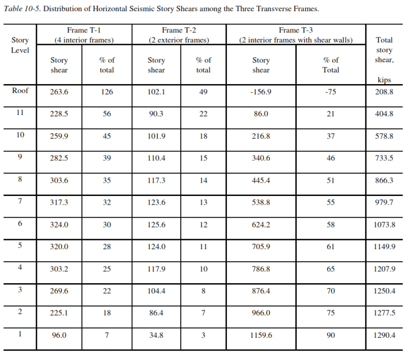
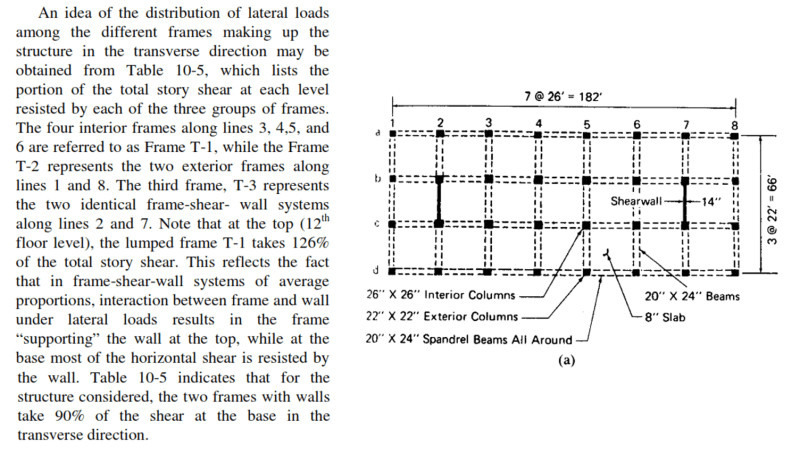
This is an example by Seismic Design Handbook by Farzad Naeim in Chapter 10.
I was confused by this sentences, quote "interaction between frame and wall under lateral loads results in the frame "supporting" the wall at the top, while at the base most of the horizontal shear is resisted by the wall" end quote. So this means that at the top (roof) level, the frame is the one who resists the story shear, am I correct? And that the story shear absorbed by shear wall will be greater than absorbed by frame, as we analyze the structure to the bottom level, if this statement is correct, then can someone explain why this happen?

The second question is how do you calculate the distribution of story shear? I have calculated the story shear for the example above manually, but I don't know how to distribute it over the frame like the table 10-5 above. How do you calculate that in Story Level 6, frame T-1 absorbed 30% of the story shear? I don't find the explanation in any chapter of the book as far as I know

Thank you, much appreciated
 
Replies continue below

Recommended for you

I am far from an expert in this area, but I presume it has to do with the modal analysis of the frames and how they behave/contribute/distribute in the different modes. At the roof level, the forces applied to the top of the frame with walls is opposite in sign to the frames without walls, making for a hard-working diaphragm.
 
The second question is how do you calculate the distribution of story shear? I have calculated the story shear for the example above manually, but I don't know how to distribute it over the frame like the table 10-5 above.

Are you talking about the distribution within the floor (i.e. diaphragm load)? If so -and if the mass and stiffness are reasonably similar across the whole floor and if we are talking a rigid diaphragm- then it's just a matter of turning that story shear into a diaphragm load (i.e. simple division).

EDIT: You can do a rigid/flexible diaphragm analysis yourself (assuming you have the relative rigidity of the frames).

Where it gets tricky is when you have something like a process building, that might have mass and/or stiffness irregularly placed. Then you are forced to do some spreadsheet work with the mode participation factors and masses.
 
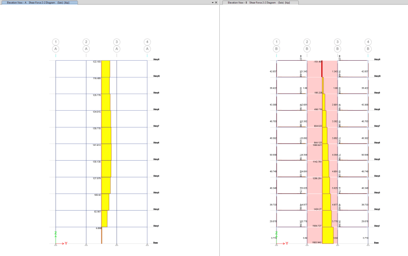
I ran an ETABS model to verify this effect. I used the member sizes and spans listed with a 12' floor-to-floor height. My seismic loading is a Y-direction only ELF load.

The snips below show the elevations of the exterior frame and the shear wall frame. The results for the exterior frame have all columns grouped as one pier, so the total shear reported is spread over the four columns. The shear wall frame has the walls as a pier and separately shows the shear in the frame elements. You can see that there is in fact load reversal in the top level of the wall.

Shear_Elevations_e7f24h.png


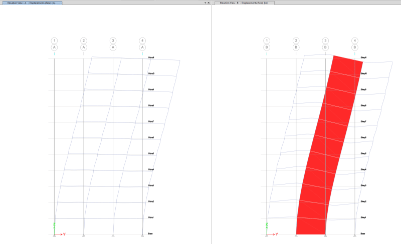
Here's a snip of the deflected shapes for the same frames:

Deflected_Shapes_eggzz9.png


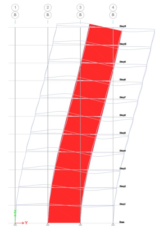
Here are the superimposed deflected shapes. At the top, the wall must want to move further in the direction of the seismic forces, and the frame starts preventing the wall from moving. I haven't fully wrapped my head around the 'why' of this phenomenon, though.

Superimposed_Defelected_Shape_ubqteu.png


As to OP's second question about how to derive the horizontal load distribution, a building of this size would usually be modeled in a structural analysis program. Relative rigidities of the elements could be used, but I'm not sure if that approach would capture this effect. One other note about relative rigidities is that the rigidity of the entire frame/wall below the point of application should be used, not the rigidity of just the level in question.
 
@WARose
I'm talking about how do you exactly calculate that at story level 6, frame T-1 absorbed 30% of the story shear?

@chris3eb
I don't understand about the pier feature on ETABS, but as how you explained it, what I understand is that the piers are a feature to group specific parts of the vertical components, so that we can view how much forces are being absorbed by the vertical component (CMIIW). And I can see that there is a load reversal in the roof level, but why is this happening?
And for my second query, I don't think they have a structural analysis program back there when they write this book, so how do they calculate the horizontal distribution of shear story?
 
The pier feature simply adds together the response of each element. So for the frame on grid A, the reported shear is the shear through all the columns added together.

I'd be interested to hear other people's thoughts about why this occurs.

They would have almost certainly used a structural analysis program to perform these calculations. There was plenty of commercially available software when this book was written (1989), and the underlaying matrix methods where known long before then.
 
I see, thank you for the explanation
 
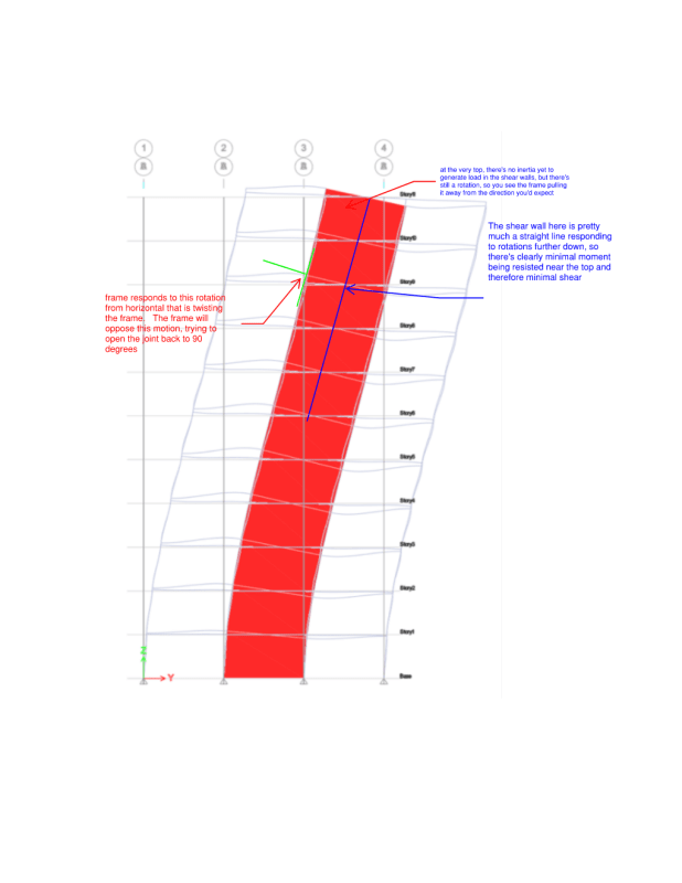
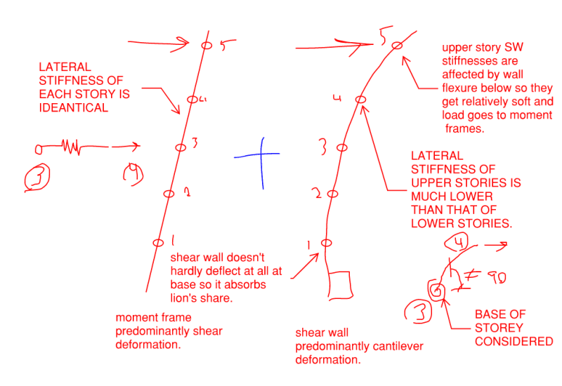
Some of this is element relative stiffness, but I just noticed a thing I've never thought about before. The shear walls respond based on rate of change of rotation (i.e. moment). The frames, though, respond fairly heavily based on rotation at the floor level where they frame in rather than the changing rotation of the structure as a whole.

See my sketch. This would explain why the frames take a fairly consistent amount of load.

This is just my pondering. I have nothing corroborating this other than looking at the diagrams in the thread.

Shear_wall_and_frame_xbzj2v.png
 
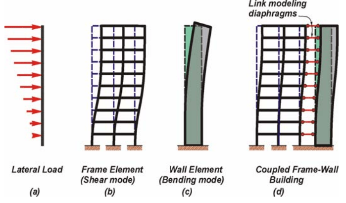
The screenshot below illustrates what is happening. While frames tend to displace in shear, walls tend to displace in flexure. Load is proportioned to the frame and wall based on relative stiffness. Because the wall curvature in the lower stories induces such large displacement at the roof, the wall stiffness at the upper stories is very small compared to the frame. However, since the wall and frame are rigidly linked to each other by the floor diaphragms, their displacements must be compatible. This causes the frame to "push back" on the wall at the upper stories to make the wall displacement compatible with it's own displacement. So the shear resisted by the frame at the roof is the story shear plus whatever amount of force is required to push the wall back to a compatible displacement.

Untitled_cocvjc.png
 
This is the same thing as what THLS and deker both said. I just find that it speaks more to my intuition when I consider only a load at the top and VLFRS's of uniform stiffness over their height.

c01_tbdb9t.png
 
The load distribution of these systems is complex and most folks will tackle the problem with FEM software.

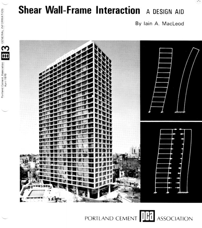
My first exposure to shear wall frame interaction was via the PCA design guide shown below. I'd love to share it but the copyright doesn't expire until 2065. That's a long wait.

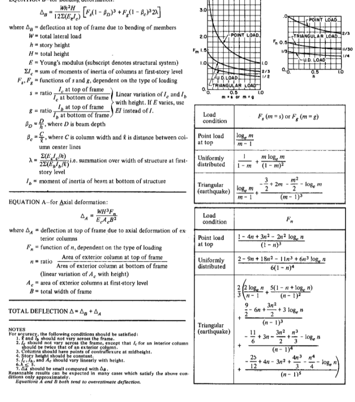
I've included a few of the PCA document procedures in the clips below so that OP can get a flavor for how much fun that might be by hand. It's not for the faint of heart or those with fading HP32S batteries.

c03_ckp0bw.png

c02_e3hyqf.png

01_w0shus.png
 
@TLHS @Deker @KootK
THANK YOU SO MUCH for the explanation, this is exactly what I've been looking for. Now it makes sense to me why the shear that was endured by the frame at the roof level is bigger than the shear resisted by shear wall. Again I appreciate deeply for your explanation, I understand a little bit better now about frame and shear wall behavior, still much to learn though, but thanks.

@KootK
It is enough, I can try to find the PCA book. Based on my recent research, there is not much where books talk a lot about horizontal distribution of seismic load, so this book might come in handy. Thanks again
 
jansenreagen said:
Based on my recent research, there is not much where books talk a lot about horizontal distribution of seismic load, so this book might come in handy.

If it's books you seek, then I recommend the two shown below, and in that order. The theory on this lands in kind of a dead zone these days. In a production environment, it's impractical to do the calcs without mobilizing FEM. So there's little interest in books that discuss the underlying behavior of these systems. The Coull book came before the mass adoption of FEM. Taranath is more recent but, then, it regurgitates a bunch of theory that he developed prior to FEM as part of his graduate studies.

The PCA thing is really more of a short monograph than a book per se. It's inexpensive to procure.

Only a small portion of the Taranath book gets into lateral behavior. That said, he hits the torsional behavior of groups of open cross sections pretty hard and in a fashion that I've not seen elsewhere. Sectorial coordinates of warping and all that Jazz. It's a tour de force in that regard. The fancy math gets neutered a bit when one considers cracked sections but the same is generally true of ETABS and the like.

c01_max4rc.png


c02_nvnwwm.png
 
Status
Not open for further replies.

Part and Inventory Search

Sponsor