Eng-Tips is the largest engineering community on the Internet

Intelligent Work Forums for Engineering Professionals

  • Congratulations waross on being selected by the Tek-Tips community for having the most helpful posts in the forums last week. Way to Go!

Straightness based GD&T understanding 1

Status
Not open for further replies.

thatdanielxy

Mechanical
Nov 28, 2018
1
0
0
SG
What's the correct understanding on below straightness definition?
Capture_gp40ue.jpg
 
Replies continue below

Recommended for you

Generally, straightness, when combined with the size dimension, refers to derived median line.
The second frame represents straightness per 1 inch as opposed to total straightness.
BUT
The MMC modifier creates condition where size tolerance and geometric tolerance are interdependent, which means both size tolerance and geo tolerance must be present.

Unfortunately the size is only given "open" one-way tolerance ("MAX") which makes it impossible to properly calculate virtual condition.
The size dimension needs both upper and lower tolerances for control to be fully legal.

"For every expert there is an equal and opposite expert"
Arthur C. Clarke Profiles of the future

 
Here is little something to show how combination of size and geometrical tolerance works:

Capture_jhps2z.png


As your part doesn't seem to be round, it is possible the specifying flatness instead of straightness might be more appropriate, but that's another story.

"For every expert there is an equal and opposite expert"
Arthur C. Clarke Profiles of the future
 
CH said:
Unfortunately the size is only given "open" one-way tolerance ("MAX") which makes it impossible to properly calculate virtual condition.
The size dimension needs both upper and lower tolerances for control to be fully legal.

CH,
Could you please clarify why you think the above statements are true?
 
@pmarc: You may imagine that the lower limit is zero, it will be technically correct, but will have no practical application.

"For every expert there is an equal and opposite expert"
Arthur C. Clarke Profiles of the future

 
Virtual condition woundn't be .034? If not, why?

The standard has an example of the form control applied on a unit basis, but it is RFS and the OP's example is modified at MMC.
Does it make any difference?
 
I didn't pay much attention first, but now I have question for pmarc and greenimi: what do you guys think .024 is - size, tolerance, or something else?

"For every expert there is an equal and opposite expert"
Arthur C. Clarke Profiles of the future

 
Question for the OP, is this drawing prepared to the 1994 standard or the 2009 standard?

I believe that use of the flatness symbol to control flatness of the derived median plane is new to the 2009 standard, and the 1994 standard uses the straightness symbol to control flatness of the derived median plane.

I had originally thought the .024 MAX was a size tolerance. However, the leader goes directly to the FCF, which opens the door to interpreting the .024 MAX as some type of note associated with the FCF.
 
@greenimi:
No, it's OK
So, you believe the size specified is .000-.024? Does it have a meaning to you?


"For every expert there is an equal and opposite expert"
Arthur C. Clarke Profiles of the future

 
AndrewTT said:
the leader goes directly to the FCF, which opens the door to interpreting the .024 MAX as some type of note

Nice touch. Could also be ISO:

Capture_yeyasj.png


"For every expert there is an equal and opposite expert"
Arthur C. Clarke Profiles of the future
 
CheckerHater said:
So, you believe the size specified is .000/.024? Does it have a meaning to you?

No, it does not.

But I would say that because size it is incomplete or confusing, does not mean that in this particular case the virtual condition cannot be calculated.

I agree that the minimum could be zero:

2.5 / page 26 - 2009

"MIN or MAX is placed after a dimension where other elements of the design definitely determine the other unspecified limit. Features, such as depths of holes, lengths of threads, corner radii, chamfers, etc., may be limited in this way. Single limits are used where the intent will be clear, and the unspecified limit can be zero or approach infinity and will not result in a condition detrimental to the design."
 
I agree with "note" interpretation (ISO comparison), but even in ISO the size is specified (Ø12). Can be a note showing a SIZE with no interpretation of being a size?? That is surely confusing.


I could see in some cases where you might want to refine straightness in a similar manner, however lets consider the magnitude of tolerances involved. I'll go with CH's assumption that this is in inches.

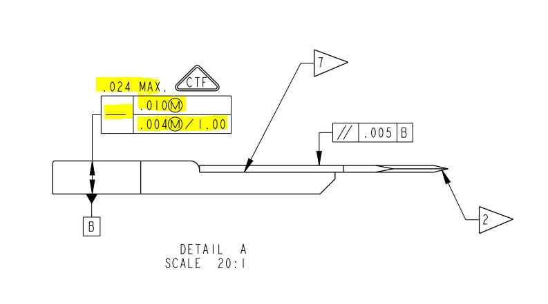
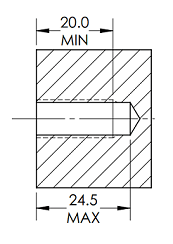
First - if .024 MAX is to be interpreted as a size dimension and tolerance, then by some rough estimation means that the entire feature is only ~.200 long and actually the FOS over which that size and straightness tolerance applies is ~.100 long. This means that by far the more stringent tolerance is the .004/1 inch and the .01 straightness tolerance would not even come into play.

Alternately, if the size dimension/tolerance is something larger, which I think might make more sense as this just seems to be extremely tiny otherwise, then the .024 MAX might apply to the allowed straightness tolerance - ie: .01 @MMC and .024 MAX as that part size departs from MMC. I'm not sure this is "kosher" but is one of the possibilities that comes to mind. Perhaps OP can clarify?

Also not to be nitpicky but wouldn't a dual(multiple segment?) control frame be more appropriate instead of a combined(composite?) control frame in this case?

Edit: Grammar
 
CH said:
So, you believe the size specified is .000/.024? Does it have a meaning to you?

It has a meaning just like you said - the lower size limit is .000 and the upper size limit is .024. But that does not mean the callout is not "fully legal". It just means someone did not care (consciously or not) that the part thickness can be very close to zero.

And most of all it does not mean that it makes "impossible to properly calculate virtual condition". As greenimi said, virtual condition for the upper portion of the tolerance frame is .034. For the lower portion it is .028.
 
@greenimi: Here is where we disagree:

You believe that if formal rule you have memorized is satisfied, the drawing is OK.

I believe that if the part cannot be made with zero thickness in real life, the drawing is ambiguous at least.

The paragraph you quote says: "MAX is placed after a dimension where other elements of the design definitely determine the other unspecified limit". Where is (are) that other element(s)?

I understand using MIN / MAX in settings like this:

MinMax_wkt0sg.png


Here you may argue that dimension actually has tolerance. :)


"For every expert there is an equal and opposite expert"
Arthur C. Clarke Profiles of the future
 
@pmarc: Like I mentioned in my post to greenimi, it's ambiguous, that makes it is not fully legal

"For every expert there is an equal and opposite expert"
Arthur C. Clarke Profiles of the future

 
CH,

I guess I should have searched the standard before asking first. Interesting.

I would have to agree with you that if we are to interpret it as a size tolerance, then while the calculation of virtual condition is possible the lack of a minimum limit other than zero in this case makes this drawing ambiguous. While our rational minds tell us that a part of zero or near zero thickness is probably not acceptable, the fact that this is not explicitly stated somehow on the drawing is an issue.

One might say that it is not ambiguous because the minimum limit is clear - in this case zero. I would say it IS ambiguous because that leaves us to interpret what exactly a part with zero or near zero thickness would look like - which is likely a futile exercise because I highly doubt this is truly the acceptable minimum limit.
 
Status
Not open for further replies.
Back
Top