Continue to Site

Eng-Tips is the largest engineering community on the Internet

Intelligent Work Forums for Engineering Professionals

  • Congratulations GregLocock on being selected by the Eng-Tips community for having the most helpful posts in the forums last week. Way to Go!

Straightness tolerance zone Figure 8-2, Y14.5-2018

Status
Not open for further replies.

Woosang

Aerospace
Dec 18, 2009
48
Below figure is captured from Y14.5-2018.
Figure (d) was not there in 1994 and 2009, but appeared in 2018.
Say I have an actual part exactly looks like figure (d). The surface is perfectly straight, but tapered as in the figure.
This figure implies that straightness of the part surface is 0.02. But I guess that the straightness should be zero.
This figure may give us a wrong perception that the straightness tolerance zone is aligned to the mating envelope axis. What do you think?
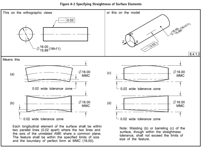
2023-01-12_16_09_08-ASME_Y14.5-2018_no_license.pdf_-_Adobe_Acrobat_Reader_32-bit_xffrzd.png
 
Replies continue below

Recommended for you


Woosang said:
...............give us a wrong perception that the straightness tolerance zone is aligned to the mating envelope axis..........

Per 8.4.1.2:

"Each longitudinal element of the surface shall lie between two parallel lines separated by the amount of the prescribed straightness tolerance and in a plane common with the axis of the unrelated AME of the feature."
 
3DDave:
Would you tell me more story?

greenimi:
That part of Y14.5 that you quoted just say that the tolerance zone is contained in the cutting plane.
That is not an answer to my question.

Is straightness of my part zero or not? That is my question.
 
Woosang,

Woosang said:
....Say I have an actual part exactly looks like figure (d). The surface is perfectly straight, but tapered as in the figure.....

In your own words......you wrote: "The surface is perfectly straight". Then? What does that mean to you?

Woosang said:
Is straightness of my part zero or not?
Now, can you answer your own question? based on "The surface is perfectly straight""


greenimi, I think Woosang is onto something. The statement you quoted from 8.4.1.2 simply refers to having the sampled element be in the same plane that cuts through the axis (so that the longitudinal element doesn't wander in a rotational manner). But that statement doesn't say anything about the tolerance zone being parallel to that axis.
I think the best answer is that someone simply goofed with picture (d). The phantom lines showing the tolerance zone should be tilted to the same angle as the sampled element; it that way the element could be even more bumpy and still pass.

John-Paul Belanger
Certified Sr. GD&T Professional
Geometric Learning Systems
 
What is really fun is the Unrelated Actual Mating Envelope on an actual conical feature can wander all over. There is no requirement for equalization nor that it be a unique solution to contraction or expansion of the similar perfect feature (not defined.) There is also no requirement that all surface elements fit a single solution simultaneously.

I can see, however, that backdriving the orientation of the part just to check the straightness of a surface element is an unwanted result. Then it becomes uninspectable without using a CMM to perform the simultaneous evaluation of a sufficient number cutting planes vs the scanned surface data.

In reality, with nothing else to orient the part, any solution as that figure describes is meaningless.

I doubt that the creator of that figure was sufficiently knowledgeable to understand the implication.

It's a bad example.
 
J-P,
The pictures shown "as made errors" and not the idealization of the parts. Per Woosang " The surface is perfectly straight" then the form error is zero.


J-P said:
The phantom lines showing the tolerance zone should be tilted to the same angle as the sampled element; it that way the element could be even more bumpy and still pass.

I agree with that. But you don't know the angle until you qualify the surface....Which is first: the chicken or the egg?
And the fact, does not matter because you are allowed, per the definition provided by the standard to move your TZ in any direction and angle, as long as the TZ stays "in a plane common with the axis of the unrelated AME of the feature.""

I don't see a big problem with this figure (d)

However, I see a problem with the text under "Means this" in fig 8-10 "Each circular element of the surface in a plane perpendicular to the axis of the UAME........"
(I know different topic alltogether)

 
Hi All,

I agree that the line elements on a perfect cone would be perfectly straight per the definition of the characteristic. The parallel-line tolerance zones are "in a plane common with the axis of the unrelated actual mating envelope of the feature". I agree that this does not mean that the zones need to be parallel to the axis (even though the zones in the other 3 examples all happen to be). The zones can freely rotate and translate within the plane. The fact that the new figure shows an incorrect example is embarrassing.

I would say that the requirement for the cutting planes to be normal to the UAME axis is an artificial restriction. As 3DDave indicated, it is there for practical purposes to specify a particular configuration of cutting planes (which may be a non-optimal configuration).

Evan Janeshewski

Axymetrix Quality Engineering Inc.
 
greenimi,

I would say that J-P is right on the money with his comments, and I would agree that there is a big problem with figure (d). It implies that the conical feature barely passes the straightness tolerance (and implies that the straightness zones must remain parallel to the axis). Both of these implications are incorrect.

Don't get me started on circularity '^).

Evan Janeshewski

Axymetrix Quality Engineering Inc.
 
axym said:
It implies that the conical feature barely passes the straightness tolerance (and implies that the straightness zones must remain parallel to the axis). Both of these implications are incorrect.

Evan,

Based on what you are concluding those statements? Are those statements opinion based statements or standard based requirements?
If standard based statements then, please provide facts........
As we all know: The figures in Y14 standards are intended only as illustrations to aid the user in understanding the practices described in the text. In other cases, figures are incomplete by intent so as to illustrate a concept or facet thereof. The
absence of figure(s) has no bearing on the applicability of the stated requirements or practice. To comply with the requirements of Y14 Standards, actual data sets shall meet the content requirements set forth in the text.

I don't see it in the same way you are seeing it. I really don't think the "implications" you provided above are true per the text provided by the standard.
Sorry that I have to disagree with such an authority, but I am trying to learn from this conversation and that's why I am doubling down :) If I am not doing it, I will not learn anything....


Diagrams are usually used to make a point, often to clarify an area that is difficult to put into words.

What point/clarification does (d) provide?

It shows that one can re-align the feature to worst-fit the tolerance zone, which is unlike other examples.

It shows that a nominally perfect feature has a large error.

I don't believe either of those aspects of the example act as an aid to understanding.
 
I also think that conical form error of a nominally cylindrical feature shouldn't affect the result of the surface straightness evaluation. As long as the line elements along the surface are straight enough, the result can be comparable to the straightness of a precisely cylindrical feature.
 
Evan said:
I would say that the requirement for the cutting planes to be normal to the UAME axis is an artificial restriction. As 3DDave indicated, it is there for practical purposes to specify a particular configuration of cutting planes (which may be a non-optimal configuration).

I don't think it's totally artificial. If a line element sample is taken from a perfectly cylindrical feature "diagonally" it will produce a bad straightness evaluation result.
 
greenimi,

The statements on what the figure implies are opinions. I agree that the definitions are in the text, and the figures only illustrate. In this case, I would say that figure 8-2 (d) implies things that the text does not say. It doesn't change (or technically contradict) the definition from the text, but it makes it very easy to misinterpret the text and get the wrong idea about how the tolerance zone is constrained. Here is another example that I believe illustrates the same thing. I've modified the means this figure from 8-7:

Fig_8-7_qvonff.png
Fig_8-7_Means_This_hfjfwj.png


The means this figure shows one of many possible orientations for the tolerance zone, and doesn't contradict anything from the text. However, I would say that the figure implies that the zone must be oriented parallel to the lower surface.

Evan Janeshewski

Axymetrix Quality Engineering Inc.
 
Status
Not open for further replies.

Part and Inventory Search

Sponsor