Continue to Site

Eng-Tips is the largest engineering community on the Internet

Intelligent Work Forums for Engineering Professionals

  • Congratulations KootK on being selected by the Eng-Tips community for having the most helpful posts in the forums last week. Way to Go!

Strange behavior when moment is applied 6

Status
Not open for further replies.

Henry26

Automotive
Oct 13, 2014
26
Hello everyone,

I've performed a non-linear quasi-static with seven components. I applied a moment in the middle component that transfer the load to the others gears. The behavior of others component are according to the expectations. But when I assign 20% of scale in deformation (in order to see the animation) the middle component has a strange behavior. Someone knows why does it happen? Follow the pictures before and after assigned the scale. I'm using Hypermesh/Optistruct.

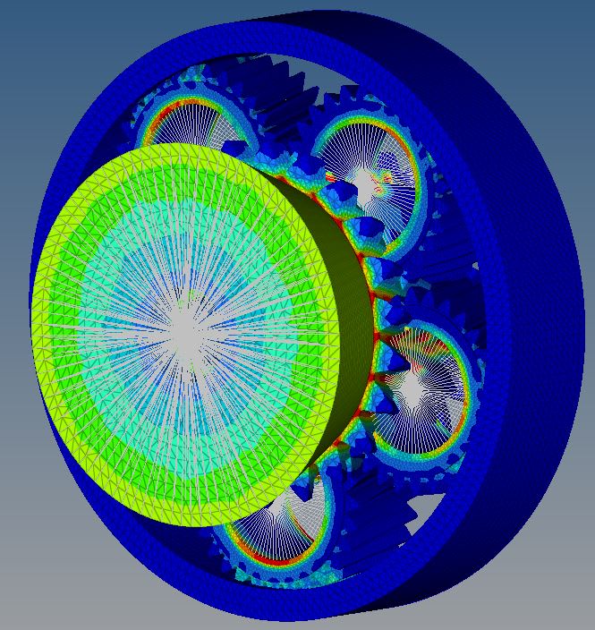
BEFORE_scale_h05luj.jpg


AFTER_scale_iphgal.jpg


Before: After:
Thanks in advance.

Henry
 
Replies continue below

Recommended for you

If those are helical gears they will generate a thrust force. And if the face of the shaft is constrained only in the direction of the axis, the resulting compressive stress would cause an expansion there. Near the planetary gears the shaft is more constrained axially which results in a smaller increase in diameter. It's not really clear to me what your boundary conditions and loads are, so that's just a guess.
 
The apparent phenomenon of shafts expanding when subject to torsion, when viewed using exaggerated displacement scale, is a common artefact of many FEA post-processing packages which compute the deformed geometry using global Cartesian coordinates rather than cylindrical coordinates.

Imagine a point on the surface of a bar with radius 100 mm, which has twisted by 1 degree, but with no radial shift; in cylindrical coordinates, the deformed coordinates are (100 mm, 1 degree), and the displacements are (0 mm, 1 degree). If we amplify the cylindrical displacements by a factor of 100, the exaggerated diaplacements would be (0 mm, 100 degrees), and we would see the shaft twisted by a bit more than 90 degrees, with no radial shift.

However, working in Cartesian coordinates, the point's undeformed coordinates are (100, 0), and after rotating by 1 degree, the displaced coordinates are (99.985, 1.745); the node has moved by (-0.015, 1.745). (Check the displaced coordinates by hand, and you will see that the true radius is still 100 mm.)

Suppose we exaggerate the Cartesian displacements by a factor of 100 - the exaggerated Cartesian displacements are now (-1.523, 174.524), so the deformed coordinates are plotted as (98.477, 174.524), which is equivalent to a plotted radius of 200.4 mm - the shaft appears to have twisted and expanded radially.

This is just an artefact of the plotting algorithm, not an indication of actual deformed shape.

 
do you mean that we have to apply common sense (as opposed to belief) when reading FEA results ?

another day in paradise, or is paradise one day closer ?
 
@rb1957:
No, there is no need for common sense (or indeed expertise or training) when creating and interpreting FEA models - as long as the plots look pretty, with lots of blue and red contours, the results can be relied upon!
/sarc

 
JXB0809 said:
red is a no-no on a plot

Agreed! [sarcasm] Adjust the result scale factor until the red disappears and all will be well. [/sarcasm] [tongue]
 
Status
Not open for further replies.

Part and Inventory Search

Sponsor