Continue to Site

Eng-Tips is the largest engineering community on the Internet

Intelligent Work Forums for Engineering Professionals

  • Congratulations SSS148 on being selected by the Eng-Tips community for having the most helpful posts in the forums last week. Way to Go!

stress analysis hand calculation-help?

Status
Not open for further replies.

TPCHOUCHOU

Mechanical
Nov 20, 2018
5
hello everyone,

i have a cabinet 90''x30''x 20 from 14 GA, 100 kg, includes cables and some electrical components. it will be installed on a train.
i need to apply 8G, 4G and 4G in the 3 directions separately and calculate the resistance of this structure.
the cabinet is mounted on 4 studs (welded to it)and fixed in two point from the top to a wall.

can someone tell me what are the formulas and equations i could use in this case please. since its a hand calculation, it seems me a bit complicated but i m sure with a little of direction i will solve it.
 
Replies continue below

Recommended for you

@ SlideruleEra an approximate solution or guidance will be very appreciated. thanks
 
@XR250 i am wandering since the cabinet is installed in a train, is it still considered static? thanks
 
@JStrucrsteel 8 G That is, when the forces acting on the body produce a resultant load of 8 times the force of gravity acting on the body's mass
 
TPCHOUCHOU - Right, F=MA, to start... the force has to be applied through the center of gravity (CG) of the box and it's contents. If the location of the CG is unknown, you will have to estimate it's location (on all three axes) based on how weight is distributed.

There are six cases, three axes, with plus and minus acceleration on each axis. Consider each, one at a time.

The problem is statically indeterminate since there are too many supports. Ignore the least important supports for each case and solve using statics for the remaining supports.

That's a beginning, see what you can do, and show us what you get. (Note: Be careful with the two vertical acceleration cases, it's easy to overlook an important component.)

[idea]
 
yes, a train carriage is considered an inertial frame.

If you're only looking at the attachment forces, then the load is applied to the CG of the cabinet. If you don't have details, then assume the geometric centroid.

another day in paradise, or is paradise one day closer ?
 
I assume these loads are from the train stopping/starting suddenly right? I've had to do similar things for seismic loads (although not quite as strong).....and typically what I have done is just simply divide the forces (equally) between the anchors. If the cabinet is fairly rigid (and can't rack) that's probably what you are going to get anyway. (Unless the CG location is really changing things.)
 
hello @SlideRuleEra
could you please explain to me the 6 cases you talked about (i'm still in learning phase)
this is what i ve tried:
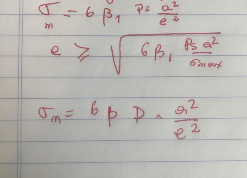
i calculated the load applied. then i have the formula for the sigma max of rectangular flat surface (in the photo)if this sigma is under those of the material then i could say that it will not break.
is it the right formula to calculate?
could you please help?
sigma_yt3gkg.jpg

cabinet_ilcj80.jpg
 
TPCHOUCHOU - Nice to see that you have started. I'll get back to the 6 cases in minute. This problem may be addressed as 4 steps:

Step 1) Locate the centroid. Using the geometric centroid, suggested by rb1957, is a reasonable way to begin. You can quickly use that to get an idea of the forces on each support. Sometimes, the centroid could be at another location. Say, there is a very heavy component at the bottom the cabinet; centroid would be lower. Or, maybe heavy electrical switch gear near the back of the cabinet; centroid would be closer the wall.

Step 2) Decide which supports to ignore to make the problem statically determinate. Ignored supports can, and probably will, change for each case.

Step 3) Calculate the forces on each support using statics, one case at a time.

Step 4) Determine if each support is adequate for the force.

Back to the 6 cases. The attached sketch shows there can be a "plus" or "minus" acceleration for each of the 3 directions:

Acceleration-1-200_gxrhjo.png


The following sketch shows acceleration "a4":

Acceleration-2-150_weujmd.png


Supports can be subjected to either shear (sliding) and/or tension/compression (overturning). Use statics to calculate the magnitude. Splitting shear forces among the 4 floor supports, per WARose, is likely reasonable.

See what you can do with this info. As I mentioned before, be careful with forces from accelerations a3 and a6.

[idea]
 
I understand you're learning, so I am being nice.

You would do better to find a mentor nearby who you can talk to directly, and in your preferred language.
Taking advice "from the Internet" is fraught with peril. Sure this "could" be a responsible site.

Take SRE's pic of an a4 load. You could analyze as a "propped cantilever" or as a simply supported "beam".
I would encourage you to try both approaches, to understand the difference, and to appreciate the conservatism (or not ?) of the SS approach.
The problem, for us, is we're not being told enough about the structure to have a true understanding of the problem.
For example, the 4 floor attachments could be in an unreinforced flat web and so much less likely to develop the out-of-plane loads that react the moment of the fixed end (of the propped cantilever).

Even us telling you which way to analyze isn't teaching you what we're looking at, what we're seeing in the structure, or why we think this method is appropriate.

another day in paradise, or is paradise one day closer ?
 
Status
Not open for further replies.

Part and Inventory Search

Sponsor