Eng-Tips is the largest engineering community on the Internet

Intelligent Work Forums for Engineering Professionals

Stress Analysis

Status
Not open for further replies.

RamaKD

Mechanical
Mar 15, 2023
7
0
0
ID
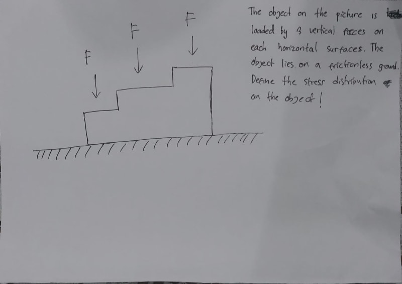
Hey guys, so I'm trying to understand how stress analysis is done through hand calculation. The picture below shows my analysis of an example problem that I'd worked at.

WhatsApp_Image_2023-03-15_at_1.55.52_PM_ne4uq7.jpg


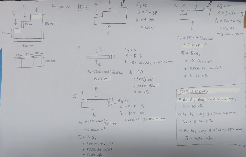
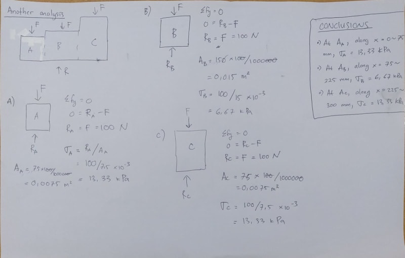
From that picture, I got the value of the stresses on the object which are
σ1, σ2, and σ3. However, if I do the analysis differently as shown in the picture below, then...

WhatsApp_Image_2023-03-15_at_5.02.38_PM_xqf0oo.jpg


I got a different value for the stresses which are σA, σB, and σC.

This got me confused, because I don't know which analysis should I use, and which distribution is the right one. Please help me solve this problem.

Thank you.
 
Replies continue below

Recommended for you

@MJCronin
It's not a homework problem. It's a made up problem by me because I was trying to understand stress distributions in a similar problem. The magnitude of the force and the dimensions is all made up, so don't mind the numbers. I just need to know how the calculations for this works.
 
@GregLocock

Okay, maybe I didn't define the problem well. Consider the object is supported by a frictionless ground, thus R is generated from the ground. There is no force on the x-direction. Maybe the picture below could illustrate the initial problem better.
WhatsApp_Image_2023-03-16_at_12.51.34_AM_lcfmwg.jpg
 
This is potentially quite a complicated problem to solve, requiring the use of "numerical methods" to take into account (among other things) the stiffness of your staircase-shaped object AND the stiffness of the ground.[ ] Also, perhaps, the manner in which your three loads F are applied (as the point loads you have shown, or as distributed loads across all or part of the step to which they are applied).

To render it amenable to hand calculation some grossly simplifying assumptions are required.[ ] In your first approach you have, in effect, assumed that the staircase is one big infinitely stiff lump (and you could have done the resulting calculation in one step rather than three).[ ] In your second approach you have assumed that the staircase is three infinitely stiff lumps sitting side-by-side and with no interactions between them.[ ] Hence different answers.[ ] Neither will be right, but the first one will be less wrong than the second.

I suspect you are also implicitly assuming that the ground will behave as a Winkler medium, but (depending upon the value of the Winkler stiffness) this is probably an acceptable assumption for a QAD* hand calculation.

* QAD = quick and dirty. Not to be confused with RAG (rough as guts).


[sub][ ]—————————————————————————————————[/sub]
[sup]Engineering mathematician/analyst.[ ] See my profile for more details.[/sup]
 
Update:

I've tried to simulate my problem using autodesk inventor, and below is the result.

WhatsApp_Image_2023-03-16_at_8.48.59_AM_mfexc0.jpg


This aligns to the results obtained through the second solution. However, it still bugs my mind because I don't understand why the first solution is wrong.
 
I believe that the external shear forces are zero so therefore so are the external moments. If each load spreads out evenly then each step has the same compressive stress and therefore the same compressive deflection so in a simplified analysis no step moves relative to any other so no shear stresses can develop. There is however a point application of loads which may cause some uneven deflections within the material which will then develop some internal shear, but this shear would not show up in a free body diagram. Also there is internal shear on planes cut at angles like found using Mohrs circle analysis.
 
@Snickster. Yes, it was my mistake to use the point load on the simulation. The load is intended to be distributed towards each stair surfaces, so it supposed to be a distributed force, not a point load.
 
Regarding why your first solution is inaccurate: That solution effectively assumes that the block is composed of three infinitely stiff blocks (of varying size), stacked on top of each other, with frictionless interfaces between them. You're assuming that the stress/pressure between the blocks is uniform across the entire interface, so the differences in pressure load applied to each stair step get averaged together, which isn't totally accurate.
 
Hey guys, I've been thinking... Isn't this just a matter of perspectives? Both analyses are right, with the difference is just on the way we choose what force is applied to what plane/area. Because from then, the principle of statics will follow, thus yield the two conclusions. Right...?
 
No. Neither analysis is accurate, since these "stairs" are presumably connected and thus form a plate which deforms as a membrane (not as three distinct "rods" next to each other), but the first analysis is wrong (see answer by Stick.) and the second one is approximate.

Is the support really perfectly immovable vertically? What are the x-axis boundary conditions? How many elements were used through-thickness (vertical direction between support and loads)? How is the vertical load distributed in reality? These things affect the results and should be considered if this is a real design problem.
 
When you make a cut you should add stresses where you cut. For your 2nd solution there'll be stresses in the cross-section on the right side of part A which will be equal but opposite in direction to stresses on the left side of part B. The same goes for the right side of part B and the left side of part C.

Also in your FEA your object should be fixed somehow which means it's not resting on a frictionless ground.
 
Status
Not open for further replies.
Back
Top