Eng-Tips is the largest engineering community on the Internet

Intelligent Work Forums for Engineering Professionals

  • Congratulations waross on being selected by the Tek-Tips community for having the most helpful posts in the forums last week. Way to Go!

Stress Classification Line Question

Status
Not open for further replies.

22west

Mechanical
Oct 31, 2002
80
0
0
CA
Hi All,

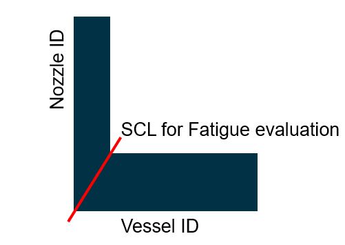
I just received a consultant's report on a pressure vessel and for each nozzle three SCLs were examined. See attached image.
I understand the need for lines 1 and 2 but what is the point of line 3? It is not on the pressure boundary - so why examine that area?
Note that the weld at line 3 was to further project the nozzle into the vessel - for an operational reason.

I am concerned about this because the classified stresses along line 3 are quite high and are governing the life of the vessel.

Thanks,
22west.
 
 https://files.engineering.com/getfile.aspx?folder=a9ee13a0-a402-48e9-b9e1-e33edbd27af6&file=SCL.jpg
Replies continue below

Recommended for you

The SCL 1 and SCL 2 is ok. SCL 3 is unnecessary. Are you sure that SCL 3 is having high stresses? I expect the stresses at SCL 2 to be higher than other SCL's.

Refer ASME Sec VIII Div 2 - Part 5, Annex 5A for example of SCL locations.
 
Hi All,

Thanks for helping me with this "sanity check".
The oddball SCLs are actually closer to the inner main wall than I show on my previous sketch, where it is more like drawing the SCL through the inner corner which is usually a nozzle red zone. See attached image. I pulled this FEA image off the web and roughly added the line I am talking about.

Most of the classified stresses on this oddball line are surely to be in the red. If you have that situation along a pressure boundary wall it is definitely not good - but in this case we are not looking through a pressure boundary wall.

The SCL stresses were also not presented in the report - nor were the local color plots where the SCLs were. Just a von mises color plot of the overall vessel

Very frustrating.

Thanks for your input.

22west.
 
 https://files.engineering.com/getfile.aspx?folder=af607f3f-1956-4123-8a4f-03f8a98f303e&file=20220129_080110.jpg
The SCL in latest post is again unnecessary, unless for fatigue evaluation.

If the linearized stresses or clear stress plots are not presented in the report, as a checker you can comment on a report that report is not compliant with the ASME Sec VIII Div 2 Part 5 - Para 2.3.3 MANUFACTURER’S DESIGN REPORT -2.3.3.3(2).
 
Thanks NRP99 for the reference on report requirements, I will check into that. On the topic of fatigue - this is indeed a report on fatigue life, and these oddball SCLs are driving the life. In this case of fatigue evaluation, how do these types of SCLs come into play?

Thanks,
22west
 
For fatigue life evaluation the SCL should be across the corner and not like the shown in your latest plot, which I should have told earlier. Like the image below-
Capture_SCL_omey8j.jpg


The SCL at this location is used to identify the peak stress value and this stress value used for the calculation of stress range ΔS[sub]p,k[/sub] and hence fatigue life.
 
All good now. I will contact the consultant and ask them why they located their SCL in that location.

Thanks to all,
22west
 
22west - the SCL that you drew in your latest sketch is 100% not a valid class line, and would likely pass none of the validation criteria. I have never, in my career, seen a SCL so bad. It truly makes me question that entire capability of your consultant. If you were to submit this to TSSA (I see that you’re from Ontario), I am confident that they would reject this.

For starters, why are they generating a SCL for a fatigue analysis? Are they trying to claim that there is a Ke factor greater than 1.0? I sure hope not based on that horrific SCL.

And NPR99 - your SCL is almost equally as bad. It would not be considered a valid class line in the context of VIII-2 and would most certainly fail any validation criteria.

Frankly, I’m appalled that this is the state of our profession in the year 2022.
 
TGS4, I agree.
The OP initially providing a sketch that doesn't reflect the true situation suggests the OP lacks any awareness. The Consultant is obviously working in a field he/she doesn't have a clue about and contributors to this thread are making it up.
How could it get any worse?
 
TGS4 said:
And NPR99 - your SCL is almost equally as bad. It would not be considered a valid class line in the context of VIII-2 and would most certainly fail any validation criteria.

This SCL line location has reference in ASME PTB-3. May be, explanation is not clear in post but the intention is clear-to use for fatigue evaluation.

TGS4 said:
Frankly, I’m appalled that this is the state of our profession in the year 2022.

Its really sad and surprising to see this comment.
 
NPR99 - exactly which example in PTB-3? I’ll bring it up with the authors and have that fixed the next time PTB-3 is revised.

Just so everyone remembers, PTB-3 dates from 2013. The Code has changed since then and engineers need to make sure that we’re using the current edition and not an example manual that references a code that is 10 years old.
 
ASME VIII-2 2021, Figure 5-A.3 (b), also shows a similar SCL. While I understand this is an example of orientation relative to stress distribution only, it isn't clear that this is the case, and probably shouldn't be used as an example when it isn't a valid SCL placement.
 
More references -

1-Title: Non-Linear Analysis Design Rules, Part 2b: Assessment of Non-Linear Benchmark Results, Produced by: World Nuclear Association, Published: September 2020. Link

Capture_SCL1_a2swsz.jpg


SCL - S22

2-Creep-Fatigue Design Studies for Process Reactor Components Subjected to Elevated Temperature Service as per ASME-NH, Science direct, 2014
Figure 3(a) in the paper. Open source paper. Link

3-Critical review of ASME III plasticity correction factors for fatigue Design-By-Analysis of nuclear power plant components, PVP2020-21267
Figure 2(SCL -8) and Figure 3 (SCL-5 and SCL -11) -Link. To see paper check Accepted author manuscript link.

All are in nuclear area so technically Sec III applies and not Sec VIII div 2. But I think its still relevant for the topic in consideration because the study considers Sec VIII div 2 as reference and fatigue evaluation using elastic analysis.
 
Status
Not open for further replies.
Back
Top