Eng-Tips is the largest engineering community on the Internet

Intelligent Work Forums for Engineering Professionals

  • Congratulations waross on being selected by the Eng-Tips community for having the most helpful posts in the forums last week. Way to Go!

Stress distribution through concrete 3

Status
Not open for further replies.

Alvarobg

Structural
Oct 8, 2015
22
ES
Hello all,
I have a doubt about stress distribution angle:
The stresses underneath concentrated forces can in general be assumed to dristribute through concrete under an angle equal to:
- 33,7º
- 45º
- depends
- other

Is there any standar related?

I am designing and the higher is the angle the more economic will be my solution.

Thank you very much
 
Replies continue below

Recommended for you

Can you give a little bit more information on this? I'm not sure if I understand clearly or if you even need this answer for your given problem.

What exactly are you designing? If it's a slab, have you attempted yield line analysis (fan shape for concentrated loads).
 
ACI 318-11, 10.14 Bearing Strength, including the Chapter 2 definition of 'A2', uses 1V:2H (63 deg). Also appears in 22.5.5.
I am sure it is more complicated than this but it's a start.
I typically use 45 degrees for, say, checking soil bearing pressure under a post bearing through a 8" slab-on-grade.
 
For a concentrated load on a wall, we use the following:

For wall design itself - use 4 x wall thickness for the width of the wall resisting the concentrated load.

For the footing design under the wall - like calvinandhobbes10 - we use a 45 deg. angle spread unless there is a door or window opening that interrupts it...then it gets truncated smaller.


Check out Eng-Tips Forum's Policies here:
faq731-376
 
Thank you all!

I have attached a scheme.

The bottom concrete must be able to resist compression transmitted through the upper concrete. Of course, it will be easier if the angle is wide, until it gets truncated.

I have checked uses 1V:2H (63 deg), but EC-2 defines 2H:1H (27 deg) which is radically different. (I am not confused with the angle and its complementary)

And it is curious but I have typically used 45 degrees for a long time. But when I tried to authenticate 45 degrees I didn't find anything.

 
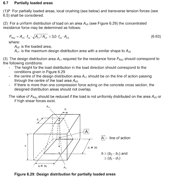
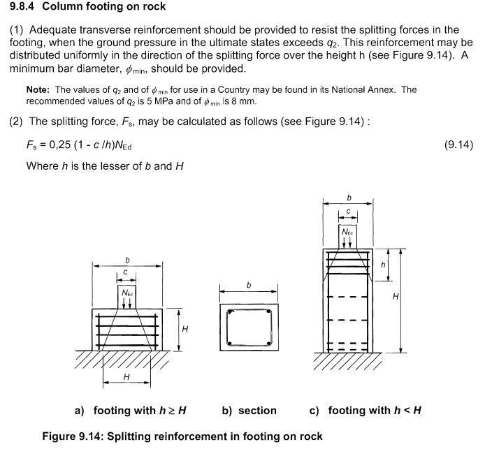
The clips below show a couple of European code sections that may find application here. There first is very similar to the provision that calvinandhobbes10 posted which would be the go to clause in North America.

If you have the opportunity, I would be inclined to reinforce the upper concrete such that you can assume the load to be spread out over the entire pedestal width. The lower concrete will likely flex and result in the upper pedestal load being delivered closer to the edges of the upper pedestal anyhow.

Capture01_bo3lrf.png

Capture02_r8vavg.png


I like to debate structural engineering theory -- a lot. If I challenge you on something, know that I'm doing so because I respect your opinion enough to either change it or adopt it.
 
Thank you.
Section 6.7 of EC-2 is equivalent to 10.14 of ACI. But in the first case the angle of transmission is 26.6º, and in the second case the angle of transmission is 63.7º. How is it possible??
 
I'm not sure that I understand. If you post the reference EC-2 provisions, I'll take a closer look at it.

I like to debate structural engineering theory -- a lot. If I challenge you on something, know that I'm doing so because I respect your opinion enough to either change it or adopt it.
 
Sorry, I did not explain well. 26.6º is the value which is deduced from the section 6.7. Taking into account that b2<3·b1 and h>b2-b1; angle maximun if b2 max, i.e. b2=3·b1, h=2·b1, so, angle=atan(((3·b1-b1)/2)/2·b1))=atan(1/2).
 
Hi, the 26.6° of the Eurocode is the maximum inclination of the tie and strut model to compute shear. You can take another angle if you want but it will impact the tie and strut model equilibrum.
 
Status
Not open for further replies.

Part and Inventory Search

Sponsor

Back
Top