DAS1001
New member
- Mar 28, 2019
- 2


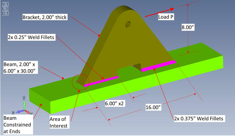
Hello, new member here. I have been asked to analyze the welded assembly shown in the attached pictures, and determine ultimate load P. The problem is, I have spent my career dealing with aluminum aircraft structures, and have basically zero knowledge about welds.
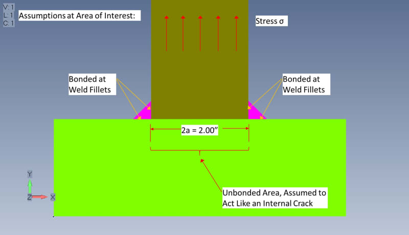
At the area of interest, the stress in the bracket will be mostly tension. The area where the two parts contact each other is not welded, only the fillets. It seems to me that this is similar to a member, loaded in tension, with an interior crack.
Can anyone give me some wisdom about how to calculate stress intensity factor for this configuration ? The literature I've been able to find online so far does not go into much detail.
Notes:
1. Parts are all low carbon steel. The bracket is AISI 1025, the beam is ASTM A36. I assume the weld rod has similar properties to these.
2. I have calculated stresses at the fillet throat as shown here: however this does not account for stress concentration at the fillet heel due to the crack tip. I have also analyzed using FEA, both linear static and nonlinear with yielding, and got widely diverging results.

![[bigsmile] [bigsmile] [bigsmile]](/data/assets/smilies/bigsmile.gif) .
.