Continue to Site

Eng-Tips is the largest engineering community on the Internet

Intelligent Work Forums for Engineering Professionals

  • Congratulations cowski on being selected by the Eng-Tips community for having the most helpful posts in the forums last week. Way to Go!

Stress on welded joint? 3

Status
Not open for further replies.

310toumad

Mechanical
May 12, 2016
63
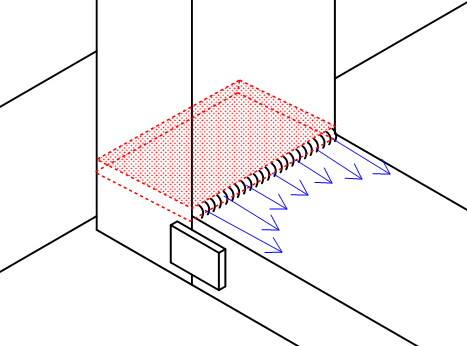
Lets say you have the set up in the diagram, with a HSS rectangular tube welded against another tube at a 90 degree angle. The connections to that vertical tube are irrelevant because I'm only concerned about this one joint. There is a cantilevered load on the end, and assume those two straps connect the tubes and are also welded all the way around. Now, if you ignore the straps it seems relatively straightforward in computing the max. stress of the weld joining the tubes. You simply look up the Iu for that particular weld group (whether its welded all the way around, 3 sides, etc.) then compute I = .707*h*Iu. Then Mc/I for bending stress and V/A for shear stress and use the Pythagorean theorem to find the max stress.

My question is, if you added those two straps on the sides to reinforce this joint, how would you go about calculating the contribution of those weld groups? How would you find the maximum stress? Can you just calculate the "I" value for the welds around the straps and add it to the value discussed above? I guess its throwing me off because for all the examples I find, they only examine one, continuous weld grouping, nothing like this. Thanks for any input.
 
 http://files.engineering.com/getfile.aspx?folder=39b57301-7594-4086-89c0-70c0f66eedb9&file=Drawing.pdf
Replies continue below

Recommended for you

you will need to calculate the moment of inertia for the entire weld group using the parallel axis theorem. You will then us MC/I to calculate the weld stress (c= dist. from neutral axis to top (or bottom) weld).
 
But the weld groups for the straps aren't even in the same plane as the bead that goes around the end cantilevered tube?
 
Blodgett (Design of Welded Structures) has some good information on how to calculate the stresses in welds.

Mike McCann, PE, SE (WA)


Whether or not you ignore the straps, you cannot assume uniform stress in the weld across the wall of the vertical HSS because the wall will bend, resulting in lower stress in the central region and higher stress near the ends of the weld. A reinforcing plate inside the vertical HSS would help to alleviate that condition.

BA
 
All the usual Mc/I solutions assume rigidity all over the place. As BA pointed out, you really do not have that rigidity at the tube to tube welds. So some valid approaches for ultimate strength, in order of my preference, include:

1) Put everything in the tube to tube welds and account for the flexibility there.

2) Put everything in the side plare welds.

3) Improve the connection to make one of the above pan out.

4) Do something expensive like like FEM to realistically asses how much force goes where.

If it's possible to do so, I think that your side plate connection would be greatly improved by running the horizontal member through the joint, beneath the vertical member.


I like to debate structural engineering theory -- a lot. If I challenge you on something, know that I'm doing so because I respect your opinion enough to either change it or adopt it.
 
Maybe its not clear from the picture, but the back of the vertical HSS butts up against a fixed tube. The top of the vertical member is hooked onto another fixed tube, so you have a force couple induced by the moment of the cantilevered load being transferred in the form of a reaction "pushing" against the bottom and pulling at the top, so I don't think the vertical member would bend much as its not floating in space.

So you're saying the connection would be stronger if the horizontal member ran underneath, and the tubes met with the vertical member butting up against the top surface of the horizontal one? Lets assume for arguments sake I switch to this set up, and following the method in Shigley's, calculate max Tau = sqrt(Tau'^2 + Tau''^2) with Tau' being V/A and Tau'' being Mc/I for a weld all the way around the tube-tube connection. Assume this is not strong enough, how do I incorporate additional welds that are NOT part of the continuous tube-tube weld into the stress calculation? (like the straps I've shown). Another example would be, lets say I have an L-bracket that is welded to the backside of the vertical member, and runs underneath the horizontal one that is welded all the way around. Why could I not simply calculate the second moment of area for this weld, add it to the tube-tube weld, and use that in the stress calculation? I'm looking for a rather simplistic approach to this, its fine if some liberties are taken in terms of assumptions regarding the actual physical reality (ie, flexibility, non-uniform stress distribution being non-factors).

Its basically finding out, if the tube-tube weld isn't strong enough, how do I calculate how much "more" weld I need to make it so?
 
310toumad said:
Maybe its not clear from the picture, but the back of the vertical HSS butts up against a fixed tube. The top of the vertical member is hooked onto another fixed tube, so you have a force couple induced by the moment of the cantilevered load being transferred in the form of a reaction "pushing" against the bottom and pulling at the top, so I don't think the vertical member would bend much as its not floating in space.

What BAretired is referring is that regardless of if/how the vertical HSS butts against a fixed tube at the back, the tensile force that exists in the top 'wall' of the horizontal HSS must be locally transferred to the face of the 'wall' of the vertical HSS (via weld), to complete the load path. BUT, the outer face of the 'wall' of the vertical HSS will deflect/distort and hence the distribution of tensile forces across the face will be non-uniform (BLUE arrows), hence why BAretired recommended a reinforcing plate, positioned as shown in RED below:

Capture_giycow.png
 
"But the weld groups for the straps aren't even in the same plane as the bead that goes around the end cantilevered tube?"

The plates/straps and the top & bottom welds are in the same plane. Calculate the moment of inertia using the plate cross section and the top/bottom welds. You will then calculate the weld stresses and plate stresses. Using the stresses in the plate, you will find the moment and shear at the plate cross section (essentially the moment and shear that would cause the stress distribution). The welds of the plate to tube can then be designed - these welds will have a vertical shear and a torque. Refer to a steel design manual and/or Blodgett if you need guidance on weld design for torque loading.

I also agree with BARetired's advice.
 
BAretired, and INgenuity's excellent posts are related to "Load path".

"Load path" is discussed in some detail in msquared48's Blodgett reference(s).

"Provide a path for the load to enter into the member that lies parallel."
====================

A welded square tube light pole fails like this in a windy environment -
The crack initiation points are the corners. Higher nominal stress, plus the concentrated stress at the toe of the welds.
The weld in the middle of the flat faces are on vacation until the very end.
 
I might be wrong about this but I am wondering if the blue/red diagram is incorrect.
I understand that the wall of the tube might (otherwise) bend BUT... doesn't the top of the horizontal tube act to stiffen the wall of the vertical tube?
 
Probably kind of an obvious point, but is there no way you can move up the adjoining member, just to make enough space for a fillet on the bottom, or at least extending the column member down just a touch. Sorry if there is a bit of an obvious piece of advice.

I think the real question lies in how to approximate the sheart stress distribution amongst the different weld groups. This in itself is a bit of headache as it depends on the relative flexibility of the joints (i.e. they're all a bit different).

I think the reinforcing plate is a good idea if nothing else.

Interesting problem.


Actually, two reinforcing plates should be used, one at the top and one at the bottom of the horizontal HSS.

Having the same width for both HSS members is not recommended as it is difficult to weld at the rounded corner of the vertical HSS. It would be better to make the horizontal HSS a little narrower, permitting a fillet weld on each side.

BA
 
310toumad:
There is something that we have really lost from or engineering methods and understanding of structures, and the way they act, from a generation ago, and the way we think we want exact, absolute, perfect solutions in today’s engineering world. If this is a one of a kind solution, it makes little sense to spend 10 hours of engineering to save 15 minutes of welding, and then to think we have a better, more perfect, more exact or absolute solution to the problem. And then, to ignore the real failure mechanisms of this type of detail as suggested by Tmoose (31DEC16, 15:29 post) If you are going to make hundreds of these, then it may make some sense to finesse the solution a bit. You have been given some good advice in the posts above. If you read btwn. the lines a bit, you will see that they are all heading in the same direction, and generally warning against the same potential problems on this joint. I have seen this joint tackled with some rigor through FEA and the young engineer ended up with a bunch of areas with unexplained nasty high stresses (red blotches in the stress printout picture) which he didn’t know what to do with. Partly the structure wasn’t modeled with a fine enough mesh, and party the software didn’t know what to do with discontinuities or sharp changes in stress direction.

In my world, I would take the canti. moment with the two horiz. welds, t&b, pretty straight forward fillet welds or PJP welds. BA’s advice (30DEC16, 23:00 post) and Ingenuity’s sketch (31DEC16, 4:14 post) are pretty straight forward and important to understand. The bulging of the wall of the vert. HSS as it is loaded is important to understand, as it transfers some of its load, from mid member, out to the sides of the joint, due to its flexibility. I would make the two vert. welds take the shear loads, although these two welds are nasty flare-bevel-groove welds btwn. the end of the horiz. canti. and the round corners of the vert. HSS. These welds are really difficult to do well, and doubly so where they transition into the t&b horiz. welds. At these four corner locations the stresses in the welds are a max. and the potential for inferior welds and defects are at their max. too. That being said, I would now make my straps differently than yours, to protect against these high stress areas and potential stress raisers, etc. I want to make my straps transfer the loads from the webs of the horiz. canti. member into the webs of the vert. member. I would make my straps “L” shaped plates, 6" +/- out onto the horiz. member and 6" +/- up onto the vert. member, with generous radiuses on all of the corners. These plates should be a little narrower in width than the side dimensions of the HSS members so they can be welded to the HSS members with a continuos fillet weld to the sides of the HSS members right at (near) the tangent points of the corner radiuses of the HSS corners. I would design these “L” shaped straps to take a good share of the moment at that joint, that is, the outer 2/3rds. of each leg of the “L”would react against the moment. That’s a bit of belt and suspenders. but conservative. We really don’t know exactly how to design any finer, in detail, than that, because we have no easy way to account for the stress raisers and potential fairly natural/common defects at the max. stress regions of the joint. From the load path, stress flow standpoint, you might be better off if you made that 90̊ corner from a solid block of steel, where the vert. HSS member and the horiz. HSS member each butted into the solid steel block with CPJ butt welds to the solid block, you would likely have more confidence in the weld quality, particularly at the corners.
 
Hi 310toumad

I would ditch the small reinforcing pads and place gussets plates on top of the horizontal section but in line with the wall thickness of the horizontal section and angle them back to the vertical section again keeping them in line with the vertical wall section thickness, that way the load is transferred through the edges of both sections.
You can weld around the gusset plates both down the sides and across the top of the horizontal section and if you extend the vertical leg below the horizontal section you can add gussets there too. Doing this should make obtaining the weld moment of inertia much easier for the stress calculation.

“Do not worry about your problems with mathematics, I assure you mine are far greater.” Albert Einstein
 
310 said:
if the tube-tube weld isn't strong enough, how do I calculate how much "more" weld I need to make it so?

You don't. At least not without resorting fancier methods such as FEM etc as I mentioned previously. The issue at play here is:

1) You've got two distinctly different load resisting mechanisms at play here (HSS/HSS welds and reinforcing plate welds).

2) Your two load resisting mechanisms are of different stiffness. The reinforcing plate path will likely be the stiffer of the two.

3) Since welds are, in general, considered non-ductile, you can't yield one of your mechanisms and hope to retain it's capacity until the more flexible method kicks in additively.

Were I a betting man, I would guess that your reinforcing plate welds and the bits of HSS/HSS weld nearest the corners will draw the lion's share of the load initially with the HSS/HSS welds between corners doing relatively little. Then the reinforcing plate and corner welds would rupture and load would redistribute to the HSS/HSS welds between the corners. Unfortunately, those welds probably aren't strong enough to do the job on their own so they, too, can be expected to fail. And that leaves you with no capacity.

In various AISC documents, there is some precedent for designing welds for 1.25 times the anticipated stress when there is uncertainty regarding stress distribution. You could do something like that here but, in many respects, that's still a crap shoot.

310 said:
So you're saying the connection would be stronger if the horizontal member ran underneath, and the tubes met with the vertical member butting up against the top surface of the horizontal one? Lets assume for arguments sake I switch to this set up, and following the method in Shigley's, calculate max Tau = sqrt(Tau'^2 + Tau''^2) with Tau' being V/A and Tau'' being Mc/I for a weld all the way around the tube-tube connection. Assume this is not strong enough, how do I incorporate additional welds that are NOT part of the continuous tube-tube weld into the stress calculation? (like the straps I've shown)

If it were me, I'd run the horizontal piece through, use the larger reinforcing plate and weld groups that would facilitate, and make the reinforcing plate load resisting mechanism take 100% of the load in the joint on it's own. Short of not reinforcing at all, I think that this would be the cheapest alternative to fabricate. You wouldn't even need to bother with the HSS/HSS welds unless there were a non-structural reason to do so (corrosion / aesthetics).

310 said:
Another example would be, lets say I have an L-bracket that is welded to the backside of the vertical member, and runs underneath the horizontal one that is welded all the way around. Why could I not simply calculate the second moment of area for this weld, add it to the tube-tube weld, and use that in the stress calculation?

Firstly, you wouldn't use such a bracket because it would be an inefficient and difficult to evaluate way of transferring flexural tension or compression around the corner of the joint. Secondly, you've still got the problem of having two load resisting mechanisms available and no simple way to ascertain how much load travels through each mechanism.

310 said:
I'm looking for a rather simplistic approach to this, its fine if some liberties are taken in terms of assumptions regarding the actual physical reality (ie, flexibility, non-uniform stress distribution being non-factors).

I know, I hear you loud and clear. And, in my opinion, there is no such simplistic approach. You've got FEM which is not simplistic at all. And you've got the 1.25 X business that I mentioned that, in my personal opinion, is too crude of an approximation for this application.

I like to debate structural engineering theory -- a lot. If I challenge you on something, know that I'm doing so because I respect your opinion enough to either change it or adopt it.
 
Status
Not open for further replies.

Part and Inventory Search

Sponsor