Hi,
I want to analyze torsion of elliptical bar in Abaqus (sort of benchmark). Since this section is not predefined in Abaqus, I wonder how to obtain stress output from a beam analysis with *Beam general section. Both with section = general (defining section properties manually) and with section = meshed (importing them from the analysis of previously sketched profile). By default there are no stresses from such analyses. I've read that section points must be defined manually in both cases. However I don't understand the way it should be done. According to the documentation, for section = general I should provide local x_1 and local x_2 position of each section point. But what does local mean here ? I've tried adding coordinates as they should be according to global CSYS but then all stresses are zero.
For section = meshed the documentation states that section points should be defined prior to the beam analysis - in the section generation step. It is said that in this case one should give section point label, element numer and integration point numer. This one seems more clear but how many points should I add to obtain good results ? Just a few like Abaqus does for predefined sections ?
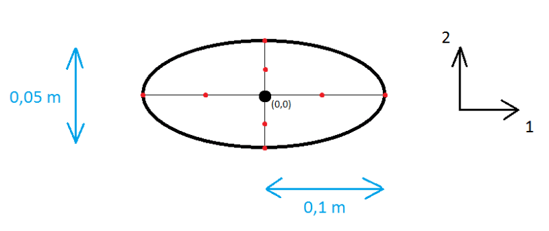
Here's my idea for the location of section points in my case:

Thanks in advance for your help
I want to analyze torsion of elliptical bar in Abaqus (sort of benchmark). Since this section is not predefined in Abaqus, I wonder how to obtain stress output from a beam analysis with *Beam general section. Both with section = general (defining section properties manually) and with section = meshed (importing them from the analysis of previously sketched profile). By default there are no stresses from such analyses. I've read that section points must be defined manually in both cases. However I don't understand the way it should be done. According to the documentation, for section = general I should provide local x_1 and local x_2 position of each section point. But what does local mean here ? I've tried adding coordinates as they should be according to global CSYS but then all stresses are zero.
For section = meshed the documentation states that section points should be defined prior to the beam analysis - in the section generation step. It is said that in this case one should give section point label, element numer and integration point numer. This one seems more clear but how many points should I add to obtain good results ? Just a few like Abaqus does for predefined sections ?
Here's my idea for the location of section points in my case:

Thanks in advance for your help
