Eng-Tips is the largest engineering community on the Internet

Intelligent Work Forums for Engineering Professionals

Stress-strain curve not respected in NL analysis 2

Status
Not open for further replies.

ecFem

New member
May 19, 2023
19
0
0
FR
Hello,

I hope you are doing well.

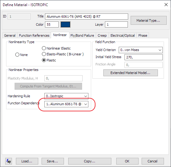
I am doing a burst analysis of a vessel. Consequently, NL material has to be introduced. Hence, I introduced the stress-strain curve and selected the Plasticity NL option. I followed what the NX Nastran's manual says :
The first point of the curve is (0,0)
The second is the strain at yield stress and the yield stress respectively.
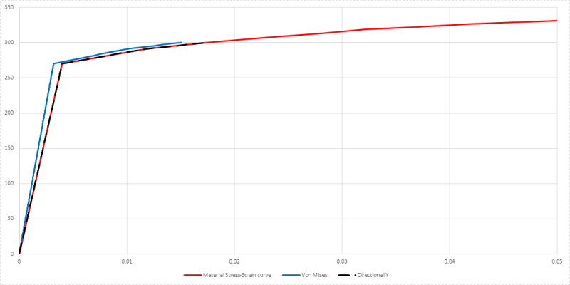
However, when I see the results, I don't retrieve the same stress-strain curve that I put on the input. Even the Young's modulus is not respected in the linear zone (I also checked that the Young's modulus that I introduced is the same that the calculated with the second point of the curve).

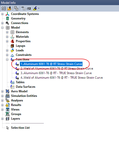
The vessel contains a welding and I am looking to obtain the stress-strain curve at this area, which is the rupture zone.
I have tried plotting :
Nonlinear Top Major Strain vs Top VM Stress
Nonlinear Top Major Strain vs Top Major Stress
Nonlinear VM Strain vs Top VM Stress (I know that VM Strain makes no sense, but MAYBE Nastran was doing something weird)
but the results are not correct.

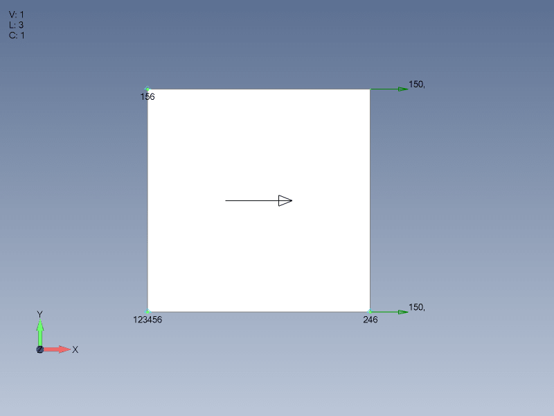
I did a small tensile test (couple of elements in line with a tensile load) and I obtain the exact same stress-strain curve that I introduced as input.

I leave the file attached if you want to take a look at it.

Thanks in advance !

Cordially,
EC
 
 https://files.engineering.com/getfile.aspx?folder=c7b04d7e-dd89-449c-b0eb-e2b3a871bda4&file=burst_test.zip
Replies continue below

Recommended for you

when you say "young's modulus is not respected" are you looking at von Mises stress or at directional values (like stress_x) ?

what if you run with linear material (to push it to use Young's modulus) ?


"Hoffen wir mal, dass alles gut geht !"
General Paulus, Nov 1942, outside Stalingrad after the launch of Operation Uranus.
 
Hello rb1957,

Thanks for your answer.

I looked at both.

I could run the analysis with a linear material, but I have no interest in doing so because I need the material to undergo plasticity.
 
bit of an "odd" model ... completely split ... what are you looking at ?

I wouldn't've put the rigid body constraints where you did (on the cut). I know it shouldn't matter, but I'd've put them something like 90 deg around the vessel.

Have you checked your model without the cut (does it inflate the way it should ?)

"Hoffen wir mal, dass alles gut geht !"
General Paulus, Nov 1942, outside Stalingrad after the launch of Operation Uranus.
 
rb1957, you are correct. I have modified ecFem model and made simple one element test model with uniaxial loading and defined material direction. Directional element stress vs strain results precisely fit material s-s curve and von Mises results don`t.

Mesh_ojc2dc.png


Curves_rmavw0.png
 
nice to be right ...

where is the NL material defined ? I expected to see a set of points, all i see is "plastic" option ??

"Hoffen wir mal, dass alles gut geht !"
General Paulus, Nov 1942, outside Stalingrad after the launch of Operation Uranus.
 
yeah, saw that. how do you see what it says there ?

"Hoffen wir mal, dass alles gut geht !"
General Paulus, Nov 1942, outside Stalingrad after the launch of Operation Uranus.
 
ok, where is this function defined ?

"Hoffen wir mal, dass alles gut geht !"
General Paulus, Nov 1942, outside Stalingrad after the launch of Operation Uranus.
 
the things you learn here !!

"Hoffen wir mal, dass alles gut geht !"
General Paulus, Nov 1942, outside Stalingrad after the launch of Operation Uranus.
 
OK, as you want.
I am not Topic Starter and don`t have problems with pressure vessel. I made test model and get some results. You can find spreadsheet with those results and test model in .dat format in archive attached to post #5. You can open it by yourself or ask ecFem to open it for you.
Goodbye.
 
yes, I saw that. I meant that I've never used this function in FeMap before ... and so I learnt something.

I think we've answered the question ... von Mises stress doesn't follow Young's modulus.

OP could test this using a quad model and changing the applied load (changing the ratio of shear stress to tension).
If the internal loads are pure axial, then vM is the same as stress_x and would follow Young's modulus.
But in more complex internal loads (axial and shear) I think vM doesn't follow Young's modulus.

"Hoffen wir mal, dass alles gut geht !"
General Paulus, Nov 1942, outside Stalingrad after the launch of Operation Uranus.
 
Thank you both very much for the your answers and the time you took responding to this topic.

I have three questions that come to my mind after reading the thread :
1. Why does the Max Principal Stress not give the correct curve ? In my opinion it should as is always taking the maximum normal stress.
2. karachun : For the curve I imagine you used also Directional Y Strain too right ? Or did you use max principal strain?
3. rb1957 : When you said it is an "odd" model because it is completely split, what did you mean by split ? I couldn't understand. You mean the welding maybe ?
4. "I think we've answered the question ... von Mises stress doesn't follow Young's modulus." That's a nice conclusion, but then : What parameter follows the introduced curve ? Max Principal Stress ? Or only the directional stresses and?

Thank you again !
 
rb1957, I misunderstood you. I thought that you already know about this function and this was some king of joke. Never mind.

ecFem I use Directional Y Strain. For some reason in Femap interface element material X axis is oriented along applied force but in results X stress is near zero and Y stress is equal to hand calculated stress.
 
"three" questions ! ... smile !!

1 ... I think the question is "wrong" !? Your material curve is being used, for the normal and shear stresses. The fact that when these stresses are combined into something else (either principal or vM) then their slope is "slightly" different is a result of the calculation, not an "error". Material curves are typically from compact tension test specimens (like stress_x). What you're seeing (as an error) is correct, IMHO.
2 ... pass
3 ... sure, could be a weld. I drilled into the model only so far (until I could pick an element, just to see)
4 ... see answer above in 1. That's why I suggested running test models to see that different shear to normal stress ratios give different vM results (and different slopes). I could work the math, but don't care to.

"Hoffen wir mal, dass alles gut geht !"
General Paulus, Nov 1942, outside Stalingrad after the launch of Operation Uranus.
 
Status
Not open for further replies.
Back
Top