NewMechE4
Mechanical
- Oct 24, 2014
- 5
Hello,
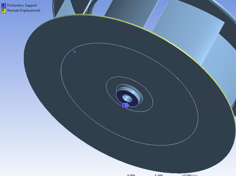
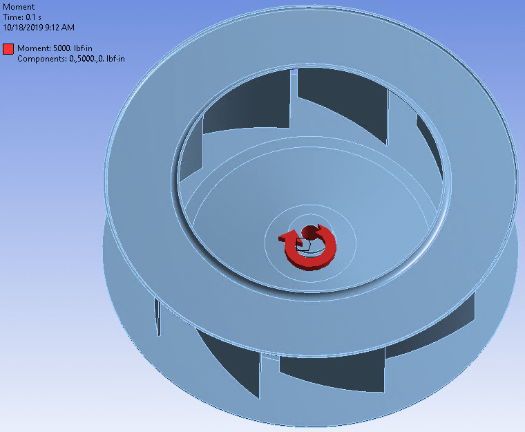
We have a customer who is experiencing fatigue failures at the hub weld of some centrifugal fan impellers which are driven by electric motors. They believe that the cause is that they are using what they call a "hard start" (they are not controlling the startup acceleration, and instead they are dumping full power to the motor.) They have requested a study that correlates the motor startup time to the fatigue life of the impeller. To do that, I performed a transient FEA of the impeller to determine the stress at the hub weld when subjected to different values of torque. The issue is that the results aren't showing any difference in stress whether I apply 1000 ft-lbs of torque or 5000 ft-lbs of torque. The stress increases as the square of the rotational velocity as expected, so the stress does increase faster with respect to time when I apply a higher torque. But I thought I might see an initial spike in stress when the torque is first applied and is opposed by the inertia of the impeller. I applied the torques as step loads, although now I am thinking maybe I should apply them as ramped loads.
Any thoughts?
Thanks for your time


