Hi everyone,
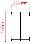
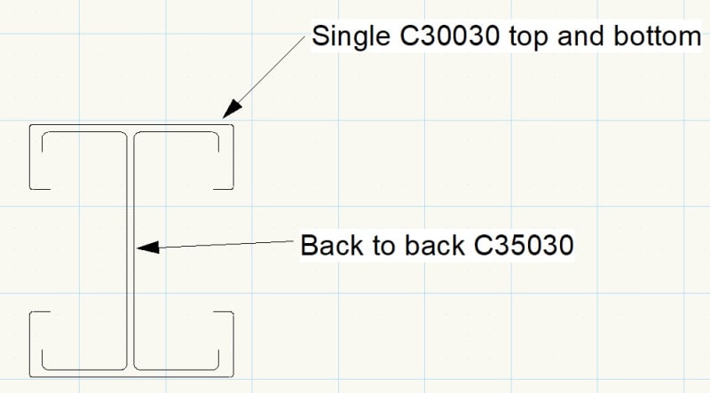
I'm wondering if anyone has any tips on how to determine the member capacity of cold formed cee sections with stiffeners attached? For example, a back to back C35030 section with C30030's bolted to each side of the web? Or a back to back C30030 section with two C35030's bolted horizontally across the top and bottom flanges, effectively doubling the area of the beam's flanges?
With the first example, I assume that the principle of superposition would apply and I can first model the back to back C350 section in a structural analysis program and find the load factor. I can then change the member to the stiffener (back to back C300) and find the load factor for that. If when added together, the load factor is greater than 1, then the 'composite' section should be strong enough. Is my logic correct?
With the second example, I have no idea how to find out the member capacity without doing FEA as most structural analysis programs do not allow for this shape of section to be entered. At the moment I'm estimating it by doubling the member capacity in bending (more than double the flange area so bending capacity should be more than double?) and making sure that the shear force doesn't exceed the shear capacity of the web of a regular back to back C35030 section. Does anyone have any ideas to be more precise?
Thank you.