Continue to Site

Eng-Tips is the largest engineering community on the Internet

Intelligent Work Forums for Engineering Professionals

  • Congratulations Danlap on being selected by the Eng-Tips community for having the most helpful posts in the forums last week. Way to Go!

Structural Analysis Problem

Feb 16, 2025
2
Hey there,

I'm doing my masters research problem on the folding of origami inspired triangulated cylinders and I am currently trying to build some code that simulates this folding process.

The simulation so far is a bunch of pin-joint bars that make up the 'folds' and will deform under an axial load (as shown below). I have managed to create a massive global stiffness matrix for these bars.
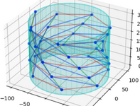
1739710904156.png

My problem is that in order to distribute the axial load to the nodes properly, I need to use a rigid plate. The paper I have attached goes into detail about various equations for compatability and equilibrium of forces and moments in the plate but my problem is that I am not sure how to apply these to be able impliment the plate into the stiffness matrix and be able to solve for forces and displacements in the structure as a whole.

If there is anyone that is able to look over what I've sent and help me or point me in the direction of somewhere else to look for answers it would be very helpful.

Thanks <3
 

Attachments

  • Screenshot 2025-02-16 at 10.54.39.png
    Screenshot 2025-02-16 at 10.54.39.png
    270.6 KB · Views: 7
Replies continue below

Recommended for you

I would model the triangular folds as ... triangles.

You want to apply a uniform compression load ? several ways ...
1) apply a uniform displacement to the top nodes, you don't need to apply a specific load, just tell the program "compress the structure 0.1in".
2) you need to react this load. You could react with an opposite displacement
3) if you apply these "loads" you need to fix the model in space, what we call "rigid body motion". About the easiest way to do this is to pick there nodes distributed about the base, like at 90 degrees, yes? ... call them 1, 2, 3. constrain N1 in three directions (2 in-plane and 1 out-of-plane) ... you can do this with model constraints (infinitely stiff constraints which prevent any deflection in these directions and tell you know much force is required to do this) or you can use "finite stiffness" constraints (have 3 rods in the 3 directions from N1, give them an area (play with this to see how sensitive or insensitive the model is) and constrain the far end. Then at N2 in two directions (1 in-plane and 1 out-of-plane), and N3 1 out-of-plane constraint. Clear as mud ? (IDK your level of understanding of FEA)

This loading makes assumptions of how the loaded nodes will deflect ... there are other ways to apply load.
 
A thought ... look into how satellites fold their antennas, and unfold them.
 
I would model the triangular folds as ... triangles.

You want to apply a uniform compression load ? several ways ...
1) apply a uniform displacement to the top nodes, you don't need to apply a specific load, just tell the program "compress the structure 0.1in".
2) you need to react this load. You could react with an opposite displacement
3) if you apply these "loads" you need to fix the model in space, what we call "rigid body motion". About the easiest way to do this is to pick there nodes distributed about the base, like at 90 degrees, yes? ... call them 1, 2, 3. constrain N1 in three directions (2 in-plane and 1 out-of-plane) ... you can do this with model constraints (infinitely stiff constraints which prevent any deflection in these directions and tell you know much force is required to do this) or you can use "finite stiffness" constraints (have 3 rods in the 3 directions from N1, give them an area (play with this to see how sensitive or insensitive the model is) and constrain the far end. Then at N2 in two directions (1 in-plane and 1 out-of-plane), and N3 1 out-of-plane constraint. Clear as mud ? (IDK your level of understanding of FEA)

This loading makes assumptions of how the loaded nodes will deflect ... there are other ways to apply load.
I agree with your idea about a displacement controlled approach to the system. However, I think imposing a uniform displacement to all the top nodes wouldn't be accurate as they are all at different elevations and the 'compressing' of the top of the structure at the point of contact with the uppermost node would impact the posiitons of the subsequent 'top' nodes
 
the uppermost nodes are the ones that are loaded, at least initially. Apply to more nodes as they contact the imaginary displacement plane.

how many nodes are there on a circle, at some z value ?
 
The upper most nodes should lie on the plate. Since you aren't accepting folding for most of them you need the current uppermost node to have edges that go straight up to the plate, creating vertical flat elements that will themselves not deform, but will carry the displacement/forces down to those edges that do see deformation.

Estimating, the node at (0, 100, 200) would have another node at (0,100, 300) with a vertical edge between them.

The result is a polygon ring of elements that are perpendicular to the top plate reaching down to the edges that will be folding.
 
I think you could save yourself a lot of time by switching to an app that is designed for simulating mechanisms, such as MSC ADAMS/View.
 

Part and Inventory Search

Sponsor