Simba12345
Mechanical
- Jul 2, 2023
- 4
Hi all,
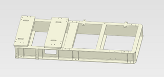
I am a graduate engineer learning FEA, I am doing a simulation on a Pump and Engine Skid frame, I would like your professional input if possible. I have different Ideas on how to apply the loads and boundary conditions, wanted to know if i am on the right path. i am using Prepomax and model was prepared in solidworks. specs are listed below.
Engine Specs:
- power: 297kW
- mass: 1285kg
- RPM: 1800RPM
-Torque: 1560 N.m
Pump Specs:
-mass: 1400 kg
Loads used in FEA simulation
pump weight with 1.5x safety factor = 20.6kN
Engine weight with 1.5x safety factor = 18.91kN
Torque with 2.5x Safety factor = 3900N.m
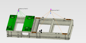
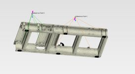
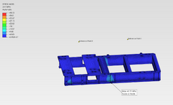
I assigned 2 reference points at the height of the input shaft on the center for both the pump and the engine. the reference points have a rigid body constraint to the pump base (green) and engine mounts (orange). the skid frame sits on 6 antivibration mounts (marked in black) I have used those as the fixed point. lastly, the torque was applied as a moment to the reference points (purple arrows, opposite directions for pump and engine). the last photo shows the results. how accurate are they? how should i go about doing the hand calculations to verify the results?
other ideas i had for the boundary conditions:
- creating reference points at the center of each mounting hole of the frame and setting those as the fixed locations
- applying the weight of the pump and engine directly to the base instead of the reference point (will this be more accurate?)
-adding another reference point for the both the engine and pump at their COG to apply the weight force from there
Thank you all in advance


