Continue to Site

Eng-Tips is the largest engineering community on the Internet

Intelligent Work Forums for Engineering Professionals

  • Congratulations SDETERS on being selected by the Eng-Tips community for having the most helpful posts in the forums last week. Way to Go!

Strut & Tie Isolated Footing

Status
Not open for further replies.

ChorasDen

Structural
Oct 19, 2021
454
This is a follow up to an older thread that can be found here: [URL unfurl="true"]https://www.eng-tips.com/viewthread.cfm?qid=392494[/url]

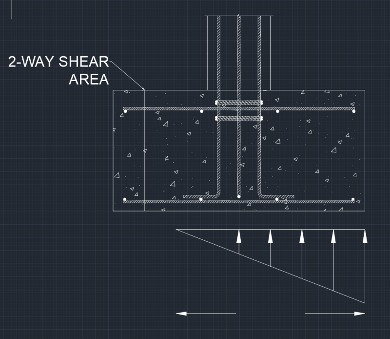
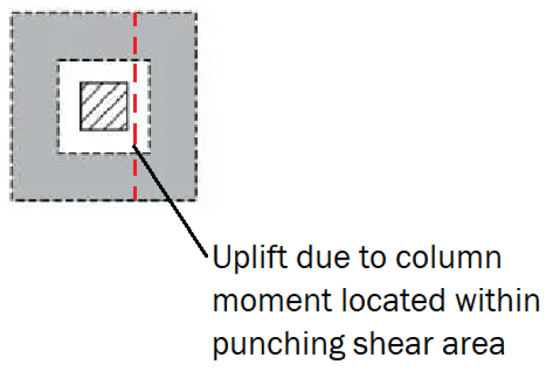
I'm trying to better understand the application of strut and tie modeling, particularly in how it relates to isolated footing design. I intend to use strut and tie modeling only when a punching shear check is not possible due to net uplift of the pressure below the footing located within the punching shear area, such that:

Punching_grwiq6.png


My question, is what is the strut and tie calculation providing? If I use a strut and tie model, do I also still need to analyze the footing for 1-way shear and induced bending, or does the strut and tie analysis resolve those issues, and make their analysis unnecessary?

I've attached a quick mock-up example I wrote as a solution, this solution is not fully fleshed out yet, but you can see the analysis provides the strut and tie forces, and will provide the required reinforcement area and development length for the ties.

Thanks for the help
 
Replies continue below

Recommended for you

OP said:
My question, is what is the strut and tie calculation providing?

1) The STM model provides a way to examine the situation and inform intelligent detailing. That's the most important thing in my opinion.

2) The STM calculation provides an alternate way to assess capacity that may be more accurate in some situations and for some proportions. Most folks would tackle this problem using sectional methods in my experience. Often I will do the same.

OP said:
If I use a strut and tie model, do I also still need to analyze the footing for 1-way shear and induced bending, or does the strut and tie analysis resolve those issues, and make their analysis unnecessary?

That depends on where you stop the strut and tie model. To conserve effort, I'd normally do STM for the joint only and then design the Bernoulli regions aspects of the footing using sectional methods. So yes to regular flexure and one way shear.
 
Thanks for the responses Kootk, but not certain I understand, can you elaborate a bit more?

2)
KootK said:
Most folks would tackle this problem using sectional methods in my experience
Assuming we fall into a situation where the moment from the column and load combinations create a scenario where there is induced uplift within the 2-way shear perimeter, are you saying you would still perform a normal 2-way shear analysis, or am I misunderstanding? Would you reduce the 2-way shear perimeter to the area of compression under the footing, or would you simply ignore 2-way shear failure, or would you use a Strut & Tie model, or something else entirely?

Kootk said:
To conserve effort, I'd normally do STM for the joint only and then design the Bernoulli regions aspects of the footing using sectional methods

By joint do you mean the compression/tension couple where the column meets the footing? If we are modeling the S&T model as resolving all the force from vertical loads and the moment couple through the struts and into the tie, can it be justified that we do not need to consider 1-way shear and flexure checks? This would obviously require a bearing area check at the base of the concrete struts to ensure we are not exceeding soil capacity.
 
OP said:
Assuming we fall into a situation where the moment from the column and load combinations create a scenario where there is induced uplift within the 2-way shear perimeter, are you saying you would still perform a normal 2-way shear analysis, or am I misunderstanding?

In that other thread, what I'd meant to convey is that, once you mobilize the column rebar to resist tensile separation at the column/footing interface, I feel that the character of the shear transfer mechanism starts to drift away from that which would be the case were there no tensile separation demand at the column/footing interface. This is different from your concern regarding uplift within the punching shear perimeter.

I feel that punching shear should be handled by way of EITHER STM or conventional, sectional checks at the discretion of the designer. Either, not both, unless one is just interested to have both values for the sake of conservatism and/or benchmarking.

I would normally check one way shear and flexure by way of conventional, sectional checks unless the proportions of the footing were such that STM checks for flexure were required. The Canadian codes requires STM for footings of some proportions. To my knowledge, the US codes do not. It is absolutely possible to check everything with STM if desired. However, that's usually a waste of effort out in the Bernoulli regions.

OP said:
By joint do you mean the compression/tension couple where the column meets the footing?

That's pretty much it but the more precise way to say it is that the "joint" is the disturbed region rather than the Bernoulli region in the assumed STM model.

OP said:
If we are modeling the S&T model as resolving all the force from vertical loads and the moment couple through the struts and into the tie, can it be justified that we do not need to consider 1-way shear and flexure checks?

The one way shear and flexural demands are present no matter which method you use to check capacity (STM / sectional). So, whichever method you choose, you need to ensure that it has an answer for those parts of the demand story.

OP said:
This would obviously require a bearing area check at the base of the concrete struts to ensure we are not exceeding soil capacity.

Right, but that's no different from the soil stress check that you would have used were you not using STM.


I don't want to inadvertently steer you down an unnecessarily arcane path here. Most folks do all of this stuff via sectional design rather than STM. I usually do all of this stuff via sectional design rather than STM. You might be well served by doing all of this stuff by sectional design rather than STM.
 
Thanks, that all helps.

I am not terribly familiar with Canadian code, I dabble a bit into CSA 086, but obviously, that doesn't address what we are discussing here. STM is acceptable per ACI as an alternate analysis procedure.

I was not familiar with STM prior to reading that thread, so developing software methodology is a way for me to understand the mechanics of this engineering approach. I agree with the need to still check 1-way failure and bending (although the design bending area may be different from the sectional approach), although I was hoping to save space on the output pdf and avoid needing to provide that check back to the user, regardless, you've helped me understand.

I agree that a traditional section method works for most situation, and when it doesn't, you can just make the footing wider. However, I do not believe the section method provides a satisfactory answer to my question above, which was tension in the 2-way area, and if the area of the footing is limiting (we can't make it wider), then I felt a need to find an alternate analysis procedure.
 
Okay, at long last, I think that I understand your concern: uplift at the soil / footing interface, not uplift at the column footing interface (what I was getting at in the other thread). If you post a cross section FBD of the footing, I may be able to speak to your particular concern.

 
Sure, here is a rough example of the concept. This is not a particular footing I am designing, this is just an attempt to approach the problem rationally. If it makes it easier and you would like me to come up with footing dimensions and loads that would fit this problem, just let me know.

From the photo, we have a bending moment induced left-to-right, causing a zero pressure location within the 2-way shear area per ACI code. This, to me, invalidates 2-way shear, unless we try to justify 2-way shear as acting on only 3 planes within the footing, rather than 4 (similar to edge columns, see ACI example below). Therefore, I propose using STM to determine validity of the footing instead of relying on section analysis that may not be appropriate for the design.

MomentFooting_ktlf9y.png


ACI_Edge_column_aweqf1.png


Is there something fundamentally invalid or incorrect with using STM rather than a 2-way shear check? Alternatively, is a 2-way shear check a reasonable approach when the footing sees a load reversal within the 2-way shear area?
 
As you surely know, most of what we know about punching shear comes from thinking about, and testing, elevated slab to column joints. In that space, it is common not to count the exterior side of the punching perimeter as contributing unless the slab extends, say, 5X the slab thickness from the column face. That would seem to speak to a similar concern to yours and it's curious that we don't seem to apply similar logic to footings. None of this has anything to do with the nature of the soil stress however.

It may be useful to remind yourself that the punching shear failure frustum is primarily supported not by the soil but, rather, by the surrounding concrete via diagonal tension resistance. Since you still have surrounding concrete on four sides, a four sided punching shear perimeter is still reasonable. You know, excepting the 5X stuff that I mentioned above.

OP said:
I agree that a traditional section method works for most situation, and when it doesn't, you can just make the footing wider.

Can you explain how making the footing wider improves matters for punching shear? If I understood that, perhaps I would better understand your perspective.

 
KootK said:
Can you explain how making the footing wider improves matters for punching shear?

Making the footing wider increases the loading area for the factored loads (which then causes the slope of the soil pressure distribution to decrease). Because the soil load slope decreases in magnitude, if we make the footing wider with a given column compression force and moment, the location of zero pressure will move outside of the 2-way shear perimeter.

Given Q = 5000lbs, M = 10000 ft-lbs, and the footing is 4ft by 4ft, we get:

P0 = Q/A - 6M/BD^2 -> 5000/16 - (6*10000)/64
P0 = -625psf

P1 = Q/A + 6M/BD^2 -> 5000/16 + (6*10000)/64
P1 = 1250psf

If we assume a linear pressure distribution from the left side of the footing to the right side, we get a location of zero pressure at x = 1.333ft from the left edge of the footing. [y = 468.75(x) - 625]

If instead, we size the footing as 4ft deep by 10ft wide we get the following:
P0 = -25psf
P1 = 275psf

Linear pressure distribution is [y = 30(x) - 25] with a zero pressure location at 0.833ft, shifting the zero pressure location further away from the footing centroid, and thus, further away from the the 2-way shear boundary area.
 
Status
Not open for further replies.

Part and Inventory Search

Sponsor