Eng-Tips is the largest engineering community on the Internet

Intelligent Work Forums for Engineering Professionals

  • Congratulations waross on being selected by the Tek-Tips community for having the most helpful posts in the forums last week. Way to Go!

Strut-and-tie model for opening joints

Status
Not open for further replies.

bugbus

Structural
Aug 14, 2018
498
0
0
AU
Hi all, I am currently developing a spreadsheet to streamline the strut-and-tie design of concrete knee joints, cantilever retaining walls, etc.

One issue I am facing is for the 'opening' case. The Australian standard states that 50% of the development of the reinforcement must extend beyond the nodal zone. This means that the face of the node can only begin where the reinforcement bend occurs (i.e. at the straight portion).

1_pwrmrq.png


2_lzwdrw.png


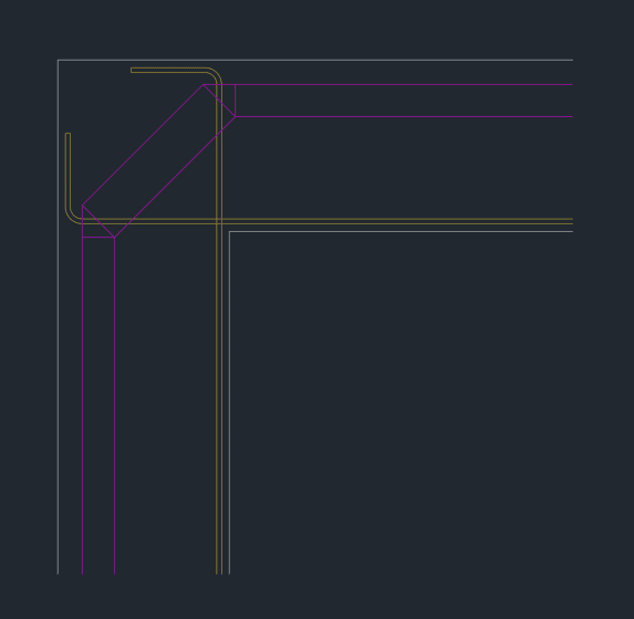
Obviously this means that the struts in the members cannot extend to the face of the member, which is often how these types of problems are presented in textbooks etc, see below.

3_hzlwrt.png


Any thoughts on how to resolve this? Or possibly this is simply the correct way of doing it?
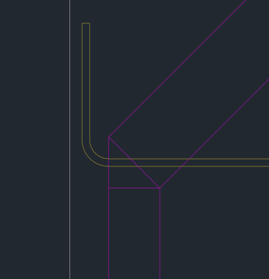
 
Replies continue below

Recommended for you

Clause 13.1.2.5?

Alternatively, ditch S&T and base design on 'the literature'? (I'm not a fan of S&T beyond qualitative stress paths)

Are you actually going to terminate the bars in the corner region as you've drawn?

Edit: if you've drawn standard cogs, I don't think they satisfy the clause. The development length is halved measured from the outside face of the bar. You don't get 50% immediately at the cog location.
 
Steve, thanks for the reply. I will check out some of the other design approaches in the literature.

The reinforcement is just drawn schematically here, mainly to show where the bends would begin.

In terms of anchorage, I've heard mixed opinions on whether the cog/hook provides an immediate 50% anchorage, my impression is that it does, but again the code is definitely unclear on that. I might look at the extended nodal region concept that's used in ACI, which makes more sense in my opinion.


The principles that inform the detailing of the moment/retaining wall condition are discussed in detail here: Link.

gusmurr said:
In terms of anchorage...

It's not actually an anchorage problem in my opinion. For moment resisting connections, what we're really dealing with is a bar bend designed to transfer rebar tension around a corner. The best STM reference for this that I know of is shown below.

gusmurr said:
The Australian standard states that 50% of the development of the reinforcement must extend beyond the nodal zone. This means that the face of the node can only begin where the reinforcement bend occurs (i.e. at the straight portion).

I believe that this represents one of the most important facets of the design of these joints. The phenomenon that you mention is precisely why these joints tend to be weaker than incoming sectional analyses would predict: because the effective flexural depth across the joint is compromised as you've observed.

c01_z4piw7.png
 
Thanks KootK

I recall the previous thread you linked quite well. I'll revisit it for sure.

I believe that this represents one of the most important facets of the design of these joints. The phenomenon that you mention is precisely why these joints tend to be weaker than incoming sectional analyses would predict: because the effective flexural depth across the joint is compromised as you've observed.

This makes sense to me, so I am wondering if it is best to keep the concrete struts somewhat internal rather than at the very face of the member?

Obviously this would result in the B regions of the members being slightly over-designed, but the joint itself having the required capacity.

 
gusmurr said:
This makes sense to me, so I am wondering if it is best to keep the concrete struts somewhat internal rather than at the very face of the member?

I'm not sure that's something that's really within your control. The struts will mostly go where they want to go based on stiffness etc.

gusmurr said:
Obviously this would result in the B regions of the members being slightly over-designed, but the joint itself having the required capacity.

Agreed. This is also, effectively, what you'll accomplish by using the efficiency factors that Celt83 posted.
 
Status
Not open for further replies.
Back
Top