4dmodeller said:
Rapt, how can you install a PT tendon into already installed precast concrete?
Until now, it was not clear to me that:
1) The precast was already installed.
2) The upper and lower wall panels were seperated by a floor slab.
OP said:
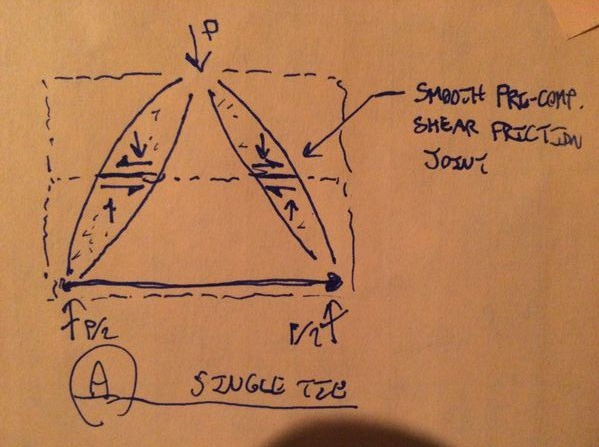
by providing antibursting reo along the strut and the tension tie at the bottom of top panel, that should prevent it no?
I don't think so. The spreading of the struts will be restrained by the reinforcing that forms the primary tension tie between struts.
OP said:
is A2 the pile? or the pile cap?
Both. Or neither. You have two separate bearing conditions that may require consideration:
1) Wall strut to pile cap.
2) Pile cap to pile.
If you are using S&T, however, your nodal stress checks should take precedence over, and obviate the need for, conventional bearing checks.
OP said:
#1 do you mean putting all the stich plate shear connection in the lower panel?
Yes, if the connections can be made to work.
OP said:
can you explain graphically?
I will if you require it but do I
really need to? This seems simple enough to explain in prose that I wouldn't need to expend 15 minutes of my life sketching and scanning.
OP said:
I feel that if i put all the stitch plates in the bottom panel, the strut and tie model wouldn't have changed. I would still need a tie at the LHS of panel. to bring the load down to the shear connection in the lower panel.
I don't see the problem. Your sketch already shows a full depth tension tie at the left hand side of the cantilevered panel. If you keep the connection to the upper panel then you'll need a tension tie connecting the upper and lower panels which seems as though it would be an necessary hassle.
I like to debate structural engineering theory -- a lot. If I challenge you on something, know that I'm doing so because I respect your opinion enough to either change it or adopt it.