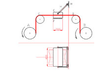
The figure shows a device for ironing, or other finishing operations, a roll of fabric.
The fabric is fed by the braked drum A, guided in the horizontal section by the idle rollers C and D and collected by the motorized drum B. In the horizontal section, the fabric is pressed by the movable steel plate E, of mass 30 kg, against the fixed plate F, also made of steel. The connecting rod H is hinged to the plate E and in a barycentric position and to the frame of the machine M.
• Calculate the crushing load on the fabric for a connecting rod angle of 45° when the machine is in operation.
• Taking into account a load acting on the fabric between the feed drum (braked) and the ironing device T0=100N, calculate the increase in load downstream of the device.
• Make a construction drawing of the Plate (E), Connecting Rod (H), Attachment to the frame group.
Assume the steel-fabric friction coefficient f=0.15
I hope someone can give me a hand.